.
Sir John . . . . . . . .
I see that these have popped up in the interim:
" If you just want to disable the sensor, you could try covering the transmitter and receiver with a sound absorbing layer (felt?) and a thick plastic sheet."
" Already tried covering with electrical tape, then tried Blu Tac but it still triggered the alarm system"
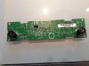
The system xmitter transducer is flooding the interior with a 40khz ultrasonic bath and "missing pulse" detection is sensed by the ultrasonic receiver transducer, in any intrusion aspect.
Your covering it up, gave a fail condition in the magnitude of the presence of a baby elephant !
HOW TO . . . . . . " DO IT TO IT"
This proximity sensor COULD send an exotic serial data stream to the Security systems main unit, OR it could send a MERE LOGIC low or logic HIGH.
I'm sort of thinking that the latter is the case. In the overall picture, making this whole EXOTIC intrusion sensor 'thang" as dumb as an adjunct plain 'ole door jamb switch.( NOTICE. . . . ."Door is ajar" )
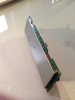
As far as now figuring it out, we neeeeeed to know which is which, as far as its three terminals are concerned. And its easiest access might be the 3 female portions of the plug that this unit mates with, since you now have that unit unplugged.
Initially you would need a ground for your metering / instrumentation and the only nearby access that I think that you might be finding for SURE will be the negative connection of your CIGAR lighter.
While you are there, also jab your DC metering positive lead up inside to the other terminal, to ascertain what your dormant battery voltage at this point is being.
Power up the alarm system so that normal voltages are now present at this female Berg connector.
Then remain keeping negative metering probe to the negative connection of your CIGAR lighter and probe the three cavities of the Berg strip connector.
If finding that you have no POINTED probe to reach inside of that small of a cavity, twirl on 10-15 turns of ~18-20 ga bare copper wire with the final short end length, it then being your mini pointee-makee-connectee probe
On reading the connectors three possibilities, you probably will find no reading on one pin, suggesting that one is being the NEGATIVE power portion of the connector and the other two pins might both be showing POSITIVE readings, and one might be close to the same value as your battery voltage.
Even the other POSITIVE reading might be pretty close to your battery voltage.
So o o o o o o here is how you sort out which is supplying a DYNAMIC battery voltage and current capability source, and the other is having but a mere STATIC voltage level with its WEAK current capabilities.
To confirm which is which, you get a 1K ( 1/4 W - 1/2 W - 1W - 2W- . . .what' cha' got cha' ?) resistor and fold its leads around so that it can "plug" into the Berg strip connector.
Then you power up the 'ole "Cataract" STV, SST, BLT* . . . . whatever . . . . in order to get its constant power to this alarm system connector .. . . . . . (* Bacon Lettuce Tomato)
Have one resistor lead plugged into the NEGATIVE and randomly select one of the other positive reading Berg connections in which to plug the other free lead of the resistor.
Meter across the resistor, and you probably will have to exert a slight sideways pressure to get a reading, since the resistors loose wire leads don't exactly even come close to making a tight friction PLUG in .
Take note of THAT voltage reading.
Do the same test with the other Berg pin possibility.
The connection which PULLED down your voltage reading the MOST is being the alarm logic output pin.
MAKING AN IN SYSTEM EVALUATION . . . . .of a procedure for "FOOLING" the system
To validate on the alarm systems " bypassing" of the intrusion alert feature.
If you were reading POSITIVE VOLTAGE in the alarm system " Sensor " pin of the Berg strip connector, the intrusion alarm portion will bring that connection to a logic LOW
on detection of intrusion.
I AM NOW ABRUPTLY STOPPING, since you might have only found ONE positive voltage on the Berg strip, in which case the system is using NEGATIVE logic.. . . . . . .
I await your findings, such that I will then only have to write up for the one pertinent condition.
Aside thought :
Remember that I had already given one solution in the manner, by the use of a low value cap to cross couple constant signal between the Xmitter an Receiver transducers.
But that involves the soldering access to the back side of the now covered up board.
The now conceived work around will only require access to the Berg plug.
73's de Edd
.