Maker Pro
Maker Pro

Broken Mini USB pin on Capture Card

Hi everyone,

I am new to these boards and pretty new to electronics and repairs, so any help would be really appreciated.

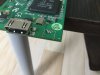
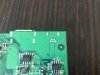
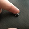
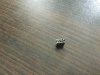
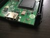
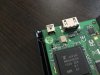
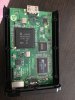
I have an older Elgato "Game Capture HD" Capture Card for capturing video via HDMI. They are known for having issues with the mini USB port. After opening it up, it is easy to see why. The mini USB port is not soldered or held down very well at all. The port is simply put into place, and it jiggles a lot. It causes problems if you bump it or move it even slightly while connected. While trying to realign the five pins on the mini USB port so it wouldn't lose contact as easy, I accidentally broke one of them off. I still have the pin, but I highly doubt that I could reattach it because it is so small. There are three pictures of the broken port.

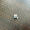
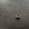
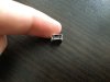
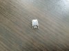
I looked around online for replacement mini USB ports, but couldn't find the exact same kind. I have attached three pictures of the closest five pin mini USB port I was able to find. I don't know much about differences between five pin mini USB ports. Is this even the right kind?

I also have attached pictures of how the port fits onto the board.

I have a little bit of soldering experience under my belt, and tools to do simple soldering, but I don't want to do anything that may break the Capture Card or my computer when I hook it up. Does anyone have any ideas on how I could get this working again? I can look up and give more detailed information if necessary.

I would really appreciate any help I can get. These capture cards are expensive, so if at all possible I would like to avoid having to buy a new one. Thanks in advance!
 

Attachments

  • IMG_2859.JPG
    IMG_2859.JPG
    516.5 KB · Views: 97
  • IMG_2860.JPG
    IMG_2860.JPG
    567.7 KB · Views: 105
  • IMG_2861.JPG
    IMG_2861.JPG
    364 KB · Views: 90
  • IMG_2862.JPG
    IMG_2862.JPG
    409.6 KB · Views: 105
  • IMG_2863.JPG
    IMG_2863.JPG
    354.2 KB · Views: 83
  • IMG_2864.JPG
    IMG_2864.JPG
    408.7 KB · Views: 93
  • IMG_2865.JPG
    IMG_2865.JPG
    322.1 KB · Views: 65
  • IMG_2866.JPG
    IMG_2866.JPG
    330.1 KB · Views: 96
  • IMG_2867.JPG
    IMG_2867.JPG
    372.3 KB · Views: 90
Last edited:
The fact that the pins are 'staggered' on one and 'straight' on the other is not an issue - the pins are still numbered 1-5 left-to-right (or vice versa if it's upside down).

If you fold the remaining pins (on the PCB) to a horizontal position you should be able to lay the new socket against the board with the new pins lying OVER the bent ones and solder them to each other. Ensure the socket is the correct way 'up' before doing this of course.....

If you are skilled enough you should even be able to bend the flat pins to match the staggered layout of the original and solder as if it was the correct one! You will have to remove the broken pins from the PCB though - take care to desolder them properly or you might remove any inter-layer plating that may be present and thus ruin everything. Not all boards have inter-layers nor do they all use them everywhere but without inspecting the area around the socket I can't tell. It certainly 'looks' as if there are no inter-layers.

With the pins connected you can feed a length of tinned copper wire through the PCB locating holes and, after pulling them tight to secure the socket to the board as best you can, solder the lead on the PCB (the bottom) and a dab on the body of the socket if you can do this quickly enough to prevent distorting the plastic that is...

Otherwise use epoxy to stick it to the PCB and give it the extra security of mounting that such stuff will afford.

Use some static precautions when doing this - just to be safe (Google the requirement if you aren't familiar)
 
Yeah, I'm thoroughly disgusted by manufacturers using mini and micro USB fragile ports to save a few millimeters of space. You'd think the industry would have learned how bad that is from the decades that consumers have had issues with 3.5mm audio jacks, but we live in a throwaway society.

You're lucky that what you have is so accessible, when it happened to my camera I just bought a battery charger and started taking the SD card out to read it instead of the complex microsurgery involved with cameras.

I'd consider running wires from the PCB to a full size USB socket, or maybe just lop the end off a USB extension cable and solder that on, using the two pads that held the frame of the prior port to the PCB, to solder a strain relief wire over the cable end, being careful not to overly melt the insulation on the cable while doing it, maybe put a thin piece of cardboard between the two if you don't have a scrap of silicone rubber, asbestos, or other heat resistant material.
 
The fact that the pins are 'staggered' on one and 'straight' on the other is not an issue - the pins are still numbered 1-5 left-to-right (or vice versa if it's upside down).

If you fold the remaining pins (on the PCB) to a horizontal position you should be able to lay the new socket against the board with the new pins lying OVER the bent ones and solder them to each other. Ensure the socket is the correct way 'up' before doing this of course.....

If you are skilled enough you should even be able to bend the flat pins to match the staggered layout of the original and solder as if it was the correct one! You will have to remove the broken pins from the PCB though - take care to desolder them properly or you might remove any inter-layer plating that may be present and thus ruin everything. Not all boards have inter-layers nor do they all use them everywhere but without inspecting the area around the socket I can't tell. It certainly 'looks' as if there are no inter-layers.

With the pins connected you can feed a length of tinned copper wire through the PCB locating holes and, after pulling them tight to secure the socket to the board as best you can, solder the lead on the PCB (the bottom) and a dab on the body of the socket if you can do this quickly enough to prevent distorting the plastic that is...

Otherwise use epoxy to stick it to the PCB and give it the extra security of mounting that such stuff will afford.

Use some static precautions when doing this - just to be safe (Google the requirement if you aren't familiar)

Thanks for the help!

I am currently in Japan and not exactly sure where I can find epoxy, but I will look around for it a bit today. That will probably be a lot easier to use.

Is there anything in particular I need to look out for when desoldering the pins? From my very amateur eyes, it doesn't seem like any layering is going on, but I will attach some pictures of the area just in case.
 

Attachments

  • image.jpg
    image.jpg
    204.3 KB · Views: 87
  • image.jpg
    image.jpg
    313.6 KB · Views: 89
Yeah, I'm thoroughly disgusted by manufacturers using mini and micro USB fragile ports to save a few millimeters of space. You'd think the industry would have learned how bad that is from the decades that consumers have had issues with 3.5mm audio jacks, but we live in a throwaway society.

You're lucky that what you have is so accessible, when it happened to my camera I just bought a battery charger and started taking the SD card out to read it instead of the complex microsurgery involved with cameras.

I'd consider running wires from the PCB to a full size USB socket, or maybe just lop the end off a USB extension cable and solder that on, using the two pads that held the frame of the prior port to the PCB, to solder a strain relief wire over the cable end, being careful not to overly melt the insulation on the cable while doing it, maybe put a thin piece of cardboard between the two if you don't have a scrap of silicone rubber, asbestos, or other heat resistant material.

I honestly couldn't believe it when I opened it up. Considering the prices they charge for some of these electronics, you would think they would take the time to make it a little sturdier, and not just lay the parts down.

I had never thought of that! I will see if I have an extra USB extension cable somewhere.
Thanks!
 
Top