Maker Pro
Maker Pro

BMS for Lithium Iron phosphate battery bank LiFePo4

I have invested in a battery bank to drive my LED night sensor spotlights. About $550 worth. I have 8 cells of 3.2V each in series to give 25.6 V nominal . They must be charged to no more than 3.55V and must not go below 2.5V . Thats the manufacturers recommendation and thats what i will stick to .

Now BMS systems are expensive . $400 and up to suit my pack.
So I found these cheap ebay boards advertised for 12V systems for $10 or so each and I thought I wonder if I can use two of these in series to monitor my bank whilst charging and discharging.

So I have them in front of me and have the pleasant task of trying to wire them up effectively.
Hmm so I'm stuck. I attach a scan of what I thought I could do but don't know how to treat the negative lines of unit one and unit two.
It seems logical to me that if i halve the pack and put a board on each there should be a way to series them and get 24Volt output . Clearly these devices work on the negative rail with a make and break circuit but I don't understand how . There are not any LEDs that light up as each cell reaches full either.

My charge system is by solar controller at 24Volts so I cant supply 12 Volts to each board separately without difficulty. Here is the ebay site for specs which are not quite what I want but will do to start me off .https://www.ebay.com.au/itm/4S-w-Balance-100A-3-2V-LiFePo4-LiFe-18650-Battery-Cell-PCB-BMS-Protection-Board/401520816753?ssPageName=STRK:MEBIDX:IT&_trksid=p2057872.m2749.l2649

Anybody able to help me out ?


Can I just hook the negatives together? C is charge input and P is Power out=load ,discharge
LiFePo4ScanofmyDiag.jpeg

IMG_20180620_115330.jpg
 
Last edited:
The standard of English on the makers website doesn't make it easy to determine what the unit actually is and what it does.
 
To get the outputs in series you would need to connect + of one to - of the other. Which means you cannot connect a single supply to the two in parallel.

I think the only way to do it is to have 2 isolated charging supplies.

Edit: or charge only one at a time.

Bob
 
If something looks too cheap to be true then guess what?
I wish you would not interject this silly stuff simply to increase your post count .Nothing is gained and it just stuffs up the thread with rubbish . I am trying to learn electronics here thats why I ask and the units work perfectly as marketed . I am trying to use them in a way not intended .
 
Last edited:
The standard of English on the makers website doesn't make it easy to determine what the unit actually is and what it does.
Have you found any chinese manual that does ? Its quite clear what it does and I have added what the solder points are . They are pretty standard for capacitor charging and battery charging protectors.
 
Bob I marked it as liked but thank you BoB. It looks like that may well be the only way

Under the hood
The 10 MOS tubes are marked

Like a sloped "T" on top


K80E06K3

001 1012

Same as these https://www.ebay.com/itm/TK80E06...


The components from the wires side left are

A2sHB the s has a stroke over it

This seems to be an FET transistor


12CB K603 Dont know what this is yet

IMG_20180621_092127.jpg IMG_20180621_092153.jpg
 
You fail to show the connections to the charging power. Unless you are using two isolated supplies, The battery on the left is shorted. This one has the + inputs and outputs common.

Bob
 
TwoBMSHX-4S-F30As-l1600.jpg This different board has the charge /discharge power coming positive from the one pos connection in red across the top. The Charge /discharge negative I have shown in black under it . The diagram given by the site shows the negative charge /discharge lead incorrectly in red ,it should be black.

So I have the negative charge/discharge lead of one unit run to the positive main line of the next unit . Clearly I don't know but would that not put the pos/negative potential of the right unit at 12 Volts and 12 volts on the left unit? Overall voltage at 24?
.
If I separated the two negative lines on the output and input on the right unit would that make any difference? The other thought was a switch on the charge negative lines to first charge one side then the other.

Trying to use gimp to add this detail to pictures is not good
 
Last edited:
1. You cannot power devices in series when the current they draw is variable.

2. You cannot charge them to 3.6 x 8 = 28.8V from a 24V source.

Get two isolated DC to DC converters to power the two BMS boards separately.

Bob
 

(*steve*)

¡sǝpodᴉʇuɐ ǝɥʇ ɹɐǝɥd
Moderator
Connecting the charger that way will stop charging as soon as one battery reaches capacity.

Three other issue you need to check carefully is what happens when these are connected in series to power a load and one BMS decides that it's batteries are dead. This will place a reverse voltage across the output of the BMS that has shut down. At worst this could destroy the BMS. A reverse biased diode across the output is a conventional method to allow power supplies to operate in series, but it would need to be capable of the full load current and may require heatsinking of the load can continue to operate in this mode.

Considering the point above, you also need to evaluate how connecting the -ve charge and -ve load terminals together will deal with this reverse voltage condition.

That is separate from whether connecting -ve load and -ve charge is appropriate. When charging you may be applying a larger voltage to the output than it would normally deliver. What happens? And especially, what happens when the charge terminates?
 
I kust looked on Ebay. BMS boards for 8 cells are available. Why are you messing with 2 desinged for 4 cells?

Bob
 
I kust looked on Ebay. BMS boards for 8 cells are available. Why are you messing with 2 desinged for 4 cells?
Bob
I did not find any . Remember we are dealing with LiFePo4 of 3.2V nominal not 3.7V 18650 types.https://en.wikipedia.org/wiki/Lithium_iron_phosphate_battery.

Boards are available from the states but the postage kills that to Australia.
http://www.batteryspace.com/Smart-L...3.2V-LFP-Cell-with-250mA-Balance-Current.aspx
Some of the cut off voltages are too high on their more expensive boards


My charger is a 70 volt solar panel putting into a MPPT controller set to cut off at 27V atm which I can program up to 28.4 if necessary when I have a working BMS . That means the cut off then would be 3.55 Volts per cell high limit and 20Volts low.

To convert to two 12 Volt supplies would be simple enough but then I would also need two boosters to up the voltage out again to 28.4V perhaps.

Steve i will have to study that a bit thanks.
 
Last edited:
Well I have just connected the first of my trial boards to my pack . So just to establish that all is well to start I have attached a single board across each half of the pack and am charging each half independently with a car battery charger of 12 Volt type. This seems to be going well and I am watching each cell too .

Confusing bit with the board specs . They are so

Specifications:
Discharge:
Continuous Discharging Current: 30A(MAX)
Instantaneous Discharge Current: 56A
Charge:
Charging Voltage: 14.8V
Charging Current: 20A (MAX)
Overcharge Protect:
Over-charge Detect: 3.75±0.05V
Protect Delay: 1300MS
Over-charge Release: 3.60±0.05V
Balance:
Detect Voltage: 3.60±0.05V
Release Voltage: 3.59±0.05V
Balance Current: 58mA
Over-discharge Protect:
Over-discharge Detect: 2.1±0.08V
Over-discharge Detect delay: 145S
Release Voltage: 2.3±0.1V
Over-current Protect:
Detect Voltage: 200mV
Detect Delay: 20mS
Current Detect: 56±10A
Release Condition: Cut Load
Inner Resistance: ≤20mΩ
Self-Consumption:
Working Current: ≤30uA
Sleep Current (when Over-discharge): ≤20uA
Working Temperature Range: -30+80℃
PCB Board Size: 56x47mm/2.2x1.85"​

So I'm wondering at what voltage it will stop charging on this board ?
It says the following
Over-charge Detect: 3.75±0.05V
Over-charge Release: 3.60±0.05V
Detect Voltage: 3.60±0.05V
Release Voltage: 3.59±0.05V
Balance Current: 58mA​

So at 3,6V it starts transfering up to 58mA along the line to the next battery cells. This stops at 3.75 V I think and the whole board shuts down.
Well thats how I see it anyway . Thats a bit too high for me so I will monitor it and stop it if thats so.

Does anybody else see these specs differently?

Don't mind the clutter , I am a risk taker for sure!
IMG_20180624_103137.jpg
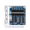
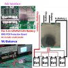
I'm using two of these boards and I have noticed that the diagrams I have been using I presumed the wire colour was wrong.Thats not so but worse than that though the board is reversed . It should be flipped. So the board I received and am using is this .

s-l1600.jpg
I think n the boards I received they might be for 3.7V 19650 type batteries . I wont know until we get to 3.7 vols on mine . The cutoffs might be different too
 
Last edited:
The 2 hour edit time limit is better but still restrictive . I just hit it again.

These better boards of 100 Amp capacity might be next but at least they show an altered connection regime ff25c274-1b30-40fa-89c7-7016c84cc229.jpg
 
Top