Maker Pro
Maker Pro

Battery charger Diode question

I'm attempting to repair a large battery charger that has 6 button diodes attached to a plate. I tested these by sending current from the transformer straight thru individual diodes. Most were visibly damaged and only one, I believe, was good. I read a forum where someone stated it would be best to repair a similar charger by replacing the button diodes with metal stud rectifier diodes, but I have few concerns I'm unclear on. I located some with a little higher amperage and voltage rating than the original diodes, but I'm unsure if I have to be concerned with ordering forward or reverse bias when choosing replacements? The original button diodes had no markings I could see. Also, I'm unsure how to attach metal stud diode to the plate? Can I simply drill a hole, insert it in, and use a locknut to attach it? I appreciate any assistance. Carl
 

Attachments

  • heatsink rectifier assembly.jpg
    heatsink rectifier assembly.jpg
    10.9 KB · Views: 161

Harald Kapp

Moderator
Moderator
I have to be concerned with ordering forward or reverse bias when choosing replacements?
What is that supposed to mean?
Forward bias is the voltage drop when current flows, typically 0.6 to 0.7 V for a siilicon diode. This parameter is in many cases not relevant for ordering.
Reverse bias ist the voltage the diode can withstand in reverse direction without breakdown. This breakdown voltage needs to be much higher than the max. expected reverse voltage (taking into account mains overvoltages etc.). This is a relevant parameter for selecting a diode. The new diodes need to be rated at the same or higher breakdown voltage as the original ones.
 
If bolting direct to the plate, then the diodes will need the correct polarity.
I would have expected three diodes to be connected to one plate and three of opposite polarity to be connected to another plate with the output from the plates
 
I'll attempt to explain why and what confuses me. I assumed this plate was some sort of rectifier, although I'm honestly unsure why there's six diodes and not four? My electronic knowledge is limited, but I recall seeing rectifier circuits with four diodes that seemed to directed current in various directions. I was concerned that the old button diodes may have had the anode facing the plate for some and the cathode for others. I wasn't sure since they were unreadable and untestable and I couldn't even locate a schematic. I didn't know if I should be concerned with current flow when ordering the stud diodes, or if they will all be the same? The only info I could find on the old button diodes was RR50 50 Amp diodes, and the new ones I ordered are 1 PC 70HTR120 70A/1200V Metal stud type Rectifier diodes. I found 6 for $22 and they're only a couple thousand miles away...so we have time. Oh, and if this project turns into a smoke bomb my only concern is I hope it's not a wimpy poof. I want my neighbors to see...lol.
 

davenn

Moderator
I'll attempt to explain why and what confuses me. I assumed this plate was some sort of rectifier, although I'm honestly unsure why there's six diodes and not four?


you still haven't done as I asked and provide a decent pic of this thing ;)


Dave
 
Four diodes are used in a single phase circuit. Six diodes are used in a three phase circuit. Which have you got?

If you are unsure of the correct connections, then work out the circuit diagram and replace the diodes with something cheap (1N400x) to get the right polarity, then when it works with light load, replace with diodes that can supply the required output current,
 
heatsink-rectifier-assembly-jpg.42714
RR50-2T.jpg

Better Dave? It's 120 Volt charger, Harold, I have at my house. A Centech 69368 charger with wheels. I purchased it at Harbor Freight a few years back...probably $100ish. I thought it may possibly be two rectifier circuits in one...or something, so I started searching duel and two rectifier circuits, but haven't found anything too similar. The four larger leads come straight off the transformer. Purchasing those original diodes ran about $70-75 with shipping. That seemed unreasonably high for a repair I wasn't certain would work. I'll continue to look around for now....thx.

Carl
 
Last edited:
Draw a digagram of what you think the circuit is like. Is the input three phase?

Where is the output conected?

The plates are part of the circuit and presumably be insulated from the case.
I have never used diodes such as you show but the red ring probably means something.
I have used stud diodes with a number and a numberR for the opposite polarity.
 
Without full particulars available on Cen-Tech 69368; If this maybe helps anyone; the rectifier assembly illustrated above is missing "two" secondary output studs which must be insulated from the rectifier plate assembly. Each individual diode button has polarity indicator ring on either side of diode(red/black)!
Q> As Carl wrote; "I'm honestly unsure why there's six diodes and not four?"
A> I'm fairly certain what is not mentioned is the charger is likely 6v/12v and likely 30/150A charger. For clarity, keynote is "6 diode buttons". What isn't certain; is if the actual "diode holder" has any internal bridge connection, and thus the leads (as per illustration above) suggests. What is obvious from the picture of diode holder assembly (above); it illustrates the "red" (+ "Anode") polarity reference band on the individual diodes facing heat-sink, "black" (- Cathode) facing holder body!
Lead configuration (as illustrated) shows parallel connections between two banks of three diodes thus I think perhaps the attached schematic will greatly assist someone!
141-240wire.jpg

If a picture is worth a thousand words; in the above schematic; for Century 141-240, Solar 1200 30/150A charger utilizes similar Century 865-574-666 Rectifier Assembly 30 Amp 6 Diode W/Breaker. The heat-sink must be insulated from Battery Charger chassis. Final note; if you upgrade to screw/bolt in diodes as Carl wrote; "70HTR120" I think the correct part should have been 70HFR120 which matches specification 70A/1200V as he referenced! Either way you still require adequate heat-sink. For 150A Charger It would just fine for my needs using (3) 50HFR120 in parallel and a FREE-CYCLED heat sink from any plasma tv.

Note: 70HF120 = Normal Polarity (Cathode to Stud)
70HFR120 = Reverse Polarity (Anode to Stud)
 
"Alternatively you can also restore your original button diode rectifier assembly; if you don't have any damaged insulators or burnt diode holders since common 10mm 50A rated 400 peak reverse voltage button diode is available in varied quantities 2, 10, 25 but looking around, you can maybe buy them less then a buck a piece!
ref: 10mm button diode, I found this source looks decent for bulk pricing!
https://www.plpbattery.com/products/button-diode-10mm-40

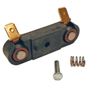
This appears to be the common battery charger diode in most older chargers. I also contacted a local industrial battery shop contact; that confirmed they normally stock these button diodes so perhaps the quickest easy solution is half dozen or more button diodes and simply utilize the original rectifier assembly. If you simply verify polarity is correct on all diodes prior to applying any AC Power, theoretically in diagram shown previous "Negative Charging Cable" is connected directly to heat sink base! Both, "Secondary Leads" are connected to "two" insulated junction studs on heat-sink because the charger design is 6v, 12v thus you can visualize (3) x 50A Diodes in parallel top side and connected by "two" junction leads to "Each" of two "Secondary Leads" at top side insulated junction.
WARNING You Must Not have "Any" connection or Secondary Leads making direct or indirect short circuit contact with heat sink Base! CLEARLY UNDERSTAND the junction studs on the heat sink are fully insulated from the heat sink base. In theory the connection layout as illustrated provides 150A Maximum Current at each SECONDARY LEAD junction point and intended "ONLY" for forward bias through all diodes "IN CORRECT POLARITY!" Before any AC power is applied or connected; insure to test each individual diode tests "open" circuit in reverse polarity using Multi-meter Diode TEST function. If charger has "Boost" function selection this is considered only temporary 150A MAX "intermittent duty cycle" purposes! THUS if you leave the charger in "Boost" for any extended either the diodes will short prematurely or the insulators on the Rectifier will suffer meltdown. Optimally I test from each secondary lead "junction" on rectifier attaching "one" test lead clipped at one junction and simultaneous testing correct polarity through each of three diodes on the "same bank" with other test lead on rectifier heat-sink base..(ALL THREE Paralleled DIODES) on each secondary lead must be installed with same matching polarity when inserting the diode buttons; so you can test diode for correct polarity before inserting diode and after complete assembly. Worst case scenario you will only blow three diodes if polarity is incorrect or defect on one of the secondary outputs! This is why they emphasize observing the polarity and testing prior to replacing the individual diodes! If your charger is tested before disassembly and you inspect the polarity and you match polarity of diodes as they are individually removed, tested, and replaced or reinstalled. There is no reason you should blow any diodes if you noted tested leads correspond matching polarity as intended by original design specification. I also perform final operation function output test (no load) using multi-meter DC VOLTAGE output test to insure correct polarity and "voltage" output to each battery output charging cable and insuring matching corresponding output battery cable clamp is correct as (Pos.) + from Ammeter = pos test lead and positive battery output cable, and (Neg.) - from Rectifier/ Circuit Breaker protection, attaching "negative test lead" at negative battery cable clamp output. Test all functions and operation prior to attaching ANY LOAD! if you don't know how to fully test Transformer without "any" AC power INPUT attached then you should not attempt any repair or you should "Always Follow the Manufacturers Original Design and Specification", Including the Schematic, which was provided only as an example of a similar design!
 
Last edited:
Top