Hi
I'm working on a project right now related to sonar. So in the hardware I have a signal of around 2KHz given to a filter and then to a LM386 audio amp circuit.
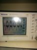
Now at the output I've connected an 8 ohm speaker. Now when I connect the setup, the speaker gives a tone. But to check if all's good I check the output with an oscilloscope and I see a lot of distortion and no proper sinewave. It's almost as if the wave is clipped but its peak to peak isnt greater than the amp supply voltage..so the amp is not saturated. So I disconnect the speaker and check again and then I find a perfect sinewave at the output of the LM386.
So I thought something is wrong with the speaker. So next I connect a signal generator generating a 2kHz sinewave and give to the speaker directly. Then I measure the waveform again at the input of speaker...Now again I get a perfect sinewave on the oscilloscope.
So I'm thinking that whatever distortion I'm getting is coz of some mismatch between speaker and amp output impedance or sort of. Now I have several stages of speaker each having its associated filter and amp. So a few stages a functioning perfectly even after connection. The only difference between the erroneous and functional stages is the IC. The functional IC is LM386N nd the defective one is LM386N-1. Both are of national semiconductor...So I try to replace all ICs with a different make...but i cant get my hands on another make..so I have to make do with this itself. Now since the amps are functional without connecting speaker, so I'm thinking theres some deeper issue. Can you give me some solution to this? Thanks
I've attached an image of the distorted waveform after connecting the speaker.
The amplifier circuit is also attached.
I'm working on a project right now related to sonar. So in the hardware I have a signal of around 2KHz given to a filter and then to a LM386 audio amp circuit.
Now at the output I've connected an 8 ohm speaker. Now when I connect the setup, the speaker gives a tone. But to check if all's good I check the output with an oscilloscope and I see a lot of distortion and no proper sinewave. It's almost as if the wave is clipped but its peak to peak isnt greater than the amp supply voltage..so the amp is not saturated. So I disconnect the speaker and check again and then I find a perfect sinewave at the output of the LM386.
So I thought something is wrong with the speaker. So next I connect a signal generator generating a 2kHz sinewave and give to the speaker directly. Then I measure the waveform again at the input of speaker...Now again I get a perfect sinewave on the oscilloscope.
So I'm thinking that whatever distortion I'm getting is coz of some mismatch between speaker and amp output impedance or sort of. Now I have several stages of speaker each having its associated filter and amp. So a few stages a functioning perfectly even after connection. The only difference between the erroneous and functional stages is the IC. The functional IC is LM386N nd the defective one is LM386N-1. Both are of national semiconductor...So I try to replace all ICs with a different make...but i cant get my hands on another make..so I have to make do with this itself. Now since the amps are functional without connecting speaker, so I'm thinking theres some deeper issue. Can you give me some solution to this? Thanks
I've attached an image of the distorted waveform after connecting the speaker.
The amplifier circuit is also attached.