Maker Pro
Maker Pro

Aqualisa Lumi 10.5kw no power

aqualisa lumi elec pics 004.jpg aqualisa lumi elec pics 001.jpg aqualisa lumi elec pics 002.jpg aqualisa lumi elec pics 003.jpg aqualisa lumi elec pics 005.jpg aqualisa lumi elec pics 006.jpg aqualisa lumi elec pics 007.jpg Installed a shower for customer and it failed first time it was used.
There was no power into control board.
Its been replaced and ive got the dead unit.

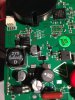
Ive found two wire wound resistors on the live and neutral wires feeding the control board(see attached pic)
On first inspection only one of these seemed to have failed (O/L) on meter, but i was getting intermittent readings from the second, and with closer looks i noticed the wire had seperated from the lead of the resistor but with movement was making contact and giving false results.

The shower was only installed and tested, which worked fine, then the next day it wouldnt turn on apparantly!! At all?
These arnt cheap , close to 500 pound.
The on off interface is a touch sensitive area on the lower face of the shower.
The only thing i can think that could of been fitter error was connecting the molex plug with power to the unit, instead of connecting then turning power on???

Anyway ive took various photos, it would be great if anyone had any info.
NOTE- The resistors were positioned inline on the Live and Neutral wires, shown in pic.3
aqualisa lumi elec pics 001.jpg aqualisa lumi elec pics 001.jpg aqualisa lumi elec pics 002.jpg aqualisa lumi elec pics 003.jpg aqualisa lumi elec pics 005.jpg aqualisa lumi elec pics 006.jpg aqualisa lumi elec pics 007.jpg aqualisa lumi elec pics 007.jpg
 
Last edited:
Are they resistors or inducors to reduce interference?
The solder joints in P3 lokk very good but can touch and blow out the inductors. The joints should be sleeved, possibly with heat shrink sleeving.

Someone may be able to translate 123K 12k mH?
 
sorry duke37 the solder joints you refer to are my handy work!! i removed the resistors/inductors????
The y were inline on both wires in question and they had sufficient heat shrink on them.
Hope thats cleared that up.
 
Are they resistors or inducors to reduce interference?
The solder joints in P3 lokk very good but can touch and blow out the inductors. The joints should be sleeved, possibly with heat shrink sleeving.

Someone may be able to translate 123K 12k mH?

Is it is an inductor ,and a very strange one here :
value=12000uH=12mH
R(DC)=30 ohm
IDCmax=110mA ,that is very low indeed.
 
Long shot but in broad terms what could cause these inductors to pop in a top end brand new unit???? Million dollar question!!! Any takers????
 
Any unexpectedly low impedance in series with the inductor could cause a current surge sufficient to blow it. So now you need to locate such an impedance :(.
The pics don't seem to show anything which would justify the high price of the unit. Has it got gold plumbing? :).
 
I know Alec_t the shower is nothing special apart from good looks on the out and a few little quirks inside and of course the 10.5kw it kicks out, setting it apart from standard electric showers.......but only a fraction!!
 
Long shot but in broad terms what could cause these inductors to pop in a top end brand new unit???? Million dollar question!!! Any takers????

That is hard to know,have you got schematics of this device?

I don't know what kind of mains voltage you have,assuming 220V and a 10.5KW heater,
It would need a 3 phase connection.
The on/off switching of such a load may cause big inrush current and voltage surge/drop.
If the house wiring connection is old/faulty that could be a problem(incising the voltage surge).
Did you notice any voltage surge/drop in the house lights when turning the unit on/off?
 
Don't be surprised if it is only single phase.
We recently had a call to a cafe which had a new instantaneous heater installed by a plumber and plugged in to a standard power outlet.
Didn't work in that outlet so they proceeded to alternatively plug it into every outlet in the shop.
Turned out to be 40A single phase(close to 10Kw)....a real problem as one can imagine....existing circuits and sub-mains already loaded to max.
 
Turned out to be 40A single phase(close to 10Kw)....a real problem as one can imagine....existing circuits and sub-mains already loaded to max.
In the UK these showers have their own dedicated 60A cable from the incoming single-phase mains distribution box.
 
dorke!! I didnt notice any issues when installing the unit.
IN the UK its 230v 50Hz
Theres no p[roblem with the mains power in the house or to the shower itself. Theres power to the molex plug that supplys the power to the control board and shower front itself.
No signs of burning or damaged components apart from these two inductors???aqualisa lumi elec pics 003.jpg aqualisa lumi elec pics 002.jpg
 
dorke!! I didnt notice any issues when installing the unit.
IN the UK its 230v 50Hz
Theres no p[roblem with the mains power in the house or to the shower itself. Theres power to the molex plug that supplys the power to the control board and shower front itself.
No signs of burning or damaged components apart from these two inductors???View attachment 23707 View attachment 23709


So, that is a 46A device,does it have it's own dedicated high current power feed?
or have you used an existing feed?
I understand the coil is on the feed to the control board and not the heater,but they are related.
What voltage is connected to the coil?

Another thing,
I think it may be very helpful if you can consult with the manufacturer here
If new it should be in the guarantee period.
 
yeh its on its own dedicated breaker in the consumer unit, new cable ran ..new bathroom.
Q...What voltage is connectyed to coil-
A...230v ac
 
yeh its on its own dedicated breaker in the consumer unit, new cable ran ..new bathroom.
Q...What voltage is connectyed to coil-
A...230v ac

Is the other unit you replaced the fault one with working fine?

I assume the coils are part of the RFI filter.
Probably some sort of inrush current to the control board caused the damage.
Did you check the board with the coils bypassed(shorted) ?

Look at the pic,
1.What is the area the blue arrow points to?
2.Can you please post a photo from the red line to the end of the board(fuse included) and show the location of the coils on it.
 

Attachments

  • aqualisa lumi elec pics 007.jpg
    aqualisa lumi elec pics 007.jpg
    242.6 KB · Views: 201
The replacement is working fine.

Ive bypassed the coils but havnt connected it upto mains power yet

The area where the arrow points is'nt populated, its footprint is for a capacitor!!!

Look at picture showing neutral wire and red wire ...the coils were soldered inline onto these two wires, directly after the molex plug! The molex plug connects to the shower unit itself and recieves power from the shower unit also, thus feeding the coils in question and the rest of the control board.
aqualisa lumi elec pics 010.jpg aqualisa lumi elec pics 015.jpg aqualisa lumi elec pics 016.jpg aqualisa lumi elec pics 017.jpg aqualisa lumi elec pics 018.jpg aqualisa lumi elec pics 019.jpg aqualisa lumi elec pics 020.jpg
 
Last edited:
Could the shower work fine without the two inductors? The shower is brand new. Just that initial turn on where the molex plug was connected with power not isolated, must have been the problem. It may have caused a short, there by burning out the inductors.
 
Top