Sir Still buildin . . . . .
Kudos ! . . . .on your photo support / supplifications . . . with them being just what is now needed..
Now after some squaring up . . .resizing to scale . . .paralllax correction . . . (triple lll is when its reallly bad). . . we then come up with the supplied photo referencing.below.
(But don't really believe it . . .as it is actually just being an optical collusion ! )
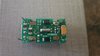
The RED line referencing to the installed xtal 1 connections confirms final board to board side relationships correctness..
READING THE BOARD . . . .
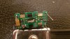
Bottom left corner we see the PINK CIRCLE J2 connector is connecting to a large ground plane foil (X3) and connects to up at the top with a gold flash via that passes thru the board at the PURPLE CIRCLE with a making of connection to the other side of the board. At the top photo you see that PURPLE via on that side connecting to the negative lead of C1, a 22 motherfarad unit, it being THE main dry tantalum E-capacitor .
Back to the bottom photo, slightly off right center.
There is another YELLOW CIRCLE gold via that has a green foil path to the left that then enters the black epoxy dome of the COB's astronomicaly large and complex logic factory . . . yet , its being microscopically, small, physically sized.
Top picture of that same YELLOW CIRCLE via , we see a branch off foil routing to the top pad of the R3 resistor.
A second foil branches off the YELLOW CIRCLE via to route under the 5100 ohm R8 resistor, to end up at the right upper BLUE CIRCLE via and a connected square pad to its right.
OBSERVATION . . .
Of the bottom photo . . . looks like that same BLUE CIRCLE via also connects to a round gold flashed contact and some gold flashed artwork resides to its bottom left.
Possibly related to a potential future or past utilization, in the manner of contacts associated with an adjunct
silicone dome with an internal graphite influxed conductive pad, that sits atop the contacts creating a simplified .
PRESS to reset.
HOWEVER . . . that might have already been used . . . .but with potential recurring situations coming up of:
Delmer Pee Dumbnuttz . . . . observes and sez . . . .( I wunners whuts this-a- hears thang duz ?) . .
.PUNCH !
With such ease of accidental / unexpected data dump they might have opted for the more involved RESET procedure.
BACK ON TOPIC . . . .
MEMORY REFRESH . . . .
A second foil branches off the YELLOW CIRCLE via to route under the 5100 ohm R8 resistor, to end up at the right upper BLUE CIRCLE via and a connected square pad to its right.
Seems like there should be a logic family value of SM resistor (10K...4.7K ) mounted between the BLUE CIRCLE's neighboring pad and the upper R2 (its missing) pad.
Now is where your eagle eyes and an ohmmeter for zero ohms /continuity is needed.
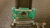
I look at the J3 corners gold flashed foil rectangle and I see no connections to it.
I see the same rectangular gold pad foils at the J2 and J1 areas , but they are being 1/2 solder flooded.
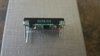
Now we move to my J4 areas outer inset photo, with its enhanced digitally dithered and averaged replotting.
What i initially thought was fine wiring going to some of the gold pads is not.
Seems like the meters frontal bezel for the unit is probably light gauge steel matte black finished and uses 4 formed tabs that pass above the cut in slots of the PCB that is just above the gold tabs.
Then you twist them inwards upon the gold tabs surfaces and the 4 then compress the front bezel and hold it in place.
ASIDE . . . you would expect the metal tabs to bite in and it could potentially/accidentally interconnect all 4 gold pads together.
But it seems that the two twisted tabs bare steel metal at the J1-J2 areas pads are intentionally solder flooded . . . right ?
Now confirm this for me . . at the J4 corners gold pad, it positively looks like there is a foil path that runs to he left
routes under the center of R9? and then possibly zig zags over and up and direct connects to J3 stake .? ? ?
Back to the J4 gold pad, confirm left corner has foil dropping down to the left one of two small gold vias.
Now the real mystery is what the little zig - zag detail from the right bottom corner.
It slants a bit at 45deg then goes right and then drops 45 again and then runs level twice the distance then STOPS.
That last oddity precludes me from determining . . . . . if that gold tab is the left end half of a corner foil (GREEN conformally coated) that would interconnect J4 stake and the R2 resistors top pad.
Or is that corner area devoid of foil and has a floating R2 pad and a cut / open interconnect between it and the J4 stake.
Your last photos positively revealed that the J1I--3--4 stakes have no connections on the COB side and the J2 tieing into ground plane.
If those are floating . . . then a RESET conversion, just might be related to a R2 install and solder connect between J4 and R2 top pad. Then follow the CURTIS reset instructions.
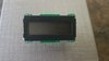
Pee Ess . . On your degree of display teardown that you did
. . . .if your display doesn't display upon reassembly . . . .you might then be in need of some further intelligentia enhancement on the exotic topic of "Zebra strips" .
I see that my professional industrial sized 39 inch crystal ball was RIGHT !
as per your final . . .just below.
(Ready to go back to the classroom ? )
Ok this might all be academic now........I touched power to the lead adjacent to Lead 2 (while the unit was powered). The display went blank and won't come back on, no digits at all......I guess I cooked it.
Thanks to everyone for your help and input anyway!
At any time after power up did you see a display, or was the pop created before you even looked at the display ?
J2 is ground plane and possibly that gold tab beside it is also . . . so you might have just ACTUALLY grounded out your + power supply for just that instant. Which should POP.
If you touched the + of the nearby yellow electrolytic just above that area you might have made a direct connection to power and bypassing any intermediate resistor, likely with no harm, but wouldn't POP.
TECHNO REFERENCING . . . . .
Thaaaaaaaaaaaaassssssssit . . .
73's de Edd . . . . .
. . . . . . . . . . .
To vacillate . . . or not to vacillate . . . .that is the question . . . . or is it ?