Maker Pro
Maker Pro

Analog domain problems

Hello, I used AD9833 to generate waveforms. I have created 3 types of waveforms and they are selectable by a switch. It worked fine for one week and I was getting sine, triangular and square waves upto 5MHz comfortably. Now, I am facing strange problem.I am able to get square wave but sine and triangular waves are not comming.
I have not changed the microcontroller program that generated the all the waveforms since 7 days. I am debugging the hardware since yesterday. Not able to find the exact reason.
I have checked the voltage at pin no.1(comp) of AD9833. It is 5V. Is it correct?
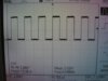
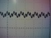
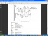
I have attached screen shots of DSO. first is square wave and 2nd is sine and triangular wave(same output for both the waves). Third ts circuit diagram.
Pls help me.
 

Attachments

  • IMG_3977.jpg
    IMG_3977.jpg
    105 KB · Views: 349
  • IMG_3981.jpg
    IMG_3981.jpg
    128.3 KB · Views: 289
  • AD9833.JPG
    AD9833.JPG
    84.1 KB · Views: 516
Last edited:
the IC requires 20mW power.

according to datasheet

i have a powersupply of 5V

transformer rating-> 1 A

so, 7805 output will be in maximum current i.e 1A according to datasheet

i connected this supply as i have to drive multiple applicatoions

so it should not get loaded

currently, i have microcontroller, LCD and Ad9833

running on that power supply

20mW = 5 x ?

so max current requirement is 10mA

my powersupply will provide much more than 10mA

i saw some tantalum capacitors becoming BROWN

so, is it the reason that sinewave and triangular wave not comming?
but these capacitors are connected between powersupply and ground. So, still do not know as how much critical aspect do they play in actual circuit. And there are disc ceramic capacitors as well doing the same function.
 
I am not able to trace the exact reason as to why the sinewave and triangular waves are not comming. This should not happen after I complete the project and it stopped working after a week. Doesn't it look strange. also, the fact is these capacitors are connected between powersupply and ground. So, still do not know as how much critical aspect do they play in actual circuit. And there are disc ceramic capacitors as well doing the same function attached parallel to tantalum capacitors. Pls check the circuit diagram in the first post.
 

(*steve*)

¡sǝpodᴉʇuɐ ǝɥʇ ɹɐǝɥd
Moderator
Can you tell me:

(1) what the voltage rating of the tantalum capacitors is, and
(2) how you determined which lead is the +ve lead, and
(3) can you confirm it's connected the right way around?
 
Top