Maker Pro
Maker Pro

Ammeter query-wiring help needed

Hi guys n gals


I bought a dual voltage/ammeter display and an adjustable current/voltage regulator with the intention of setting it up so I could monitor both from the output.

I get the voltage section, but not the ammeter.

Help with how to connect the ammeter would be most appreciated.

Here's a pic of both modules:

IMG_20150215_120001.jpg
 

davenn

Moderator
your ammeter connections goes in series between the output of the power supply and the load
I + goes to the PSU positive out
I - goes to the positive connection of the load


note there are 2 voltage connections
V in goes to the positive output of the PSU supplying power to your projects
Vcc goes to the positive of a separate PSU for supplying the display module

you will find problems often occur if you try and use the same PSU for both purposes
I killed 2 display modules doing that before I figured out the problem


Dave
 
Last edited:
Thanks for the reply, I worked out the display power and voltage metering part not long after posting, finished connecting it up after reading your answer.

so I wired things as follows:

VOLTAGE

PSU to VIN
Vcc to module + output
GND to GND

AMMETER

I+ to module + output
I- to positive binding post


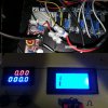
Here's a pic of my setup:

IMG_20150215_231945.jpg
 
So I switched it on and the display showed some odd numbers.

Also, the regulator on the module got extremely hot so had to shut it off to save it (hope its still ok, started to give off a slight smell, but no smoke).

Not sure why this is happening as the other modules remain unaffected and are working fine.
 
Worked out why the display reads 0, the fuse blows every time I connect the ammeter positive to the PSU out positive.

Reading is all aver the place if ammeter + is connected to the module output +.

Could the display be faulty?
 
It sounds like you are trying to put the ammeter leads directly across the power supply. This is not a good idea, and it will blow a fuse or worse.

To make it more explicit, here is what Dave is trying to tell you:

First, wire the load to the PSU the way you normally would and insure that is it working without blowing a fuse.

Now, break the connection from the PSU + to the load and wire the ammeter I+ lead to the PSU and the ammeter I- lead to the load lead that you removed from the PSU. In other words, wire the I+ and I- leads in series with the load, between the load and the PSU.

Bob
 
Like this?

IMG_20150217_231047.jpg

If so, then I think my display is faulty.

Every time I touch the ammeter + to the PSU the fuse blows.
 

davenn

Moderator
yup like that

it may well be faulty, you possibly damaged it when you connected it up incorrectly


Back in post #2, I also suggested to you that you needed a separate PSU for the display
but you didn't do that, instead you connected its Vcc connections to the output
of the supply you were supplying the load with
This is probably what damaged it and also what is causing the fuse to blow


Dave
 
I think you could be right, noob mistake thinking I could use the same power source as the only other way I wired it up was thusly:

IMG_20150218_100707.jpg


Would really like this to be self contained, is there any way of utilising the same power source without damaging it?
 

davenn

Moderator
that's no good as you are not measuring current used by the load
plus the load isn't going to have wires coming out the other side of it

maybe you should also tell us what your LOAD is ?
 
I'm making an ATX lab PSU (yeh, I know)

IMG_20150206_011836.jpg

It's just a stand in till I can afford a decent one as I've just started an EE course and figured that making one will help me learn a few things.

After reading that ATX PSUs are unregulated, I put fuses and adjustable voltage regulator modules inline with each rail (I figured they'd help to smooth things out a tad); each set to provide the corresponding voltage of the rail they're tied to).

Im trying to add an adjustable current/voltage regulator coupled with the voltage/ammeter display for a variable rail as I play with LEDs a lot.

I was hoping to hook it up so I could read the current being provided by the module so I can set it to a specific value rather than reading what is being drawn by a load.

As to a separate rail for the display (I think it's still ok as its only been on for short moments).

I wanted to move the 3 pin "kettle lead" socket on the ATX to the wall of the main box anyway so I plan to install the internals of a wall wart (to save on space) as an isolated PSU for the display.
 
Top