Hello,
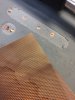
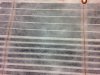
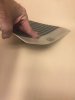
Im needing some help coming up with methods to access embedded copper metal inside a fiberglass panel. What I have is expanded copper that is embedded inside cured fiberglass. I make the fiberglass panels and want to contact the copper with a good and reliable connection. I attached a picture of a panel that is 1/8" thick that has expanded copper foil in the middle. I also attached copper rivets to sections for testing different termination ideas. In the photo you can see where Ive milled to the copper. What I am trying to do is create a reliable embedded copper tab or etc. that I can drill to acess then attach the terminal. Some panels will be thicker so the copper will be deeper down when gaining access. Since I know a lot more about making the panels in compression molding than I do electrical terminations Ive been exploring the pcb world quite a bit, mostly on digikey. My original thoughts were to drill to the copper then simply solder the posts and glue the terminal or pot the solder. Since the panels will undergo some vibration I was looking for a stronger bond, possibly mechanical. I think potting will be strong with epoxy, but a mechanical fastening with potting would be best for long term. I would like to put a threaded post or something in there but the steel molds are .125" apart when closed. Is there a way to use solder as a reliable conection for amperage up to 10A on 110vac and then mechanically fasten the terminal to the board? The more I think about this it seems Im doing exactly the same thing that goes on with pcb's, except I am trying to NOT drill through the panel. Any thoughts would help, I cut-n-pasted the links to some of the products I ordered at digikey.
Thanks!!
https://www.digikey.com/product-detail/en/on-shore-technology-inc/OSTOQ020151/ED2850-ND/1588333
https://www.digikey.com/product-det...corp/0390-0-15-01-08-27-10-0/ED5034-ND/158196
https://www.digikey.com/product-det...orp/0388-0-15-15-08-27-10-0/ED90536-ND/433904
https://www.digikey.com/product-detail/en/phoenix-contact/1778764/277-2315-1-ND/2625585
https://www.digikey.com/product-det...orp/0712-0-33-15-08-27-10-0/ED1361-ND/5176097