Maker Pro
Maker Pro

AC/DC Power Convert Questions

Hello, I have a few (noobish) questions regarding AC/DC power converters (and general electronics questions) as I am building a home-made pinball machine and will most likely use a converter to power the solenoids (Power from an outlet, converted to DC current). I can really use some advice and feedback. I have a great knowledge for pinball machines but have limited knowledge of electronics.

I'm basing my questions on this http://www.circuitspecialists.com/ps1-150w-28.html converter (28V 5.5A).

1. I understand that the range for the input AC voltage is that of a standard wall outlet/voltage for houses. How do I connect an outlet to the converter? What is the correct procedure for wiring to a converter?

2. Can the output DC voltage be adjusted to lower than 28V? Can I have one circuit using 28V and say another using 5V (for lamps)?

3. When wiring the outputs, does the direction of V+ and V- matter? Do coils have polarity?

Thanks in advance for answers.
 

davenn

Moderator
you need a standard 3 core cable that has a wall plug on one end
You strip back some main insulation ( outer sheath) to expose the 3 inner cores on the other end .... Live (Brown), Neutral (Blue) and Earth ( Green/Yellow) leads
then strip off a little of each of the insulation of those 3 leads. and solder them so the individual fine wires don't splay apart

pwrcable.jpg

OK you can see how the 3 cores have been separated and the ends stripped
also see how the fine wires of each end has been twisted up tight. they can mow be soldered and trimmer to about 0.5 cm in length
ready to put under the screw terminals


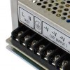
PSU.JPG


so the first 3 terminals from the left side

(AC) L and N
L = Live = Brown, N = Neutral = Blue and the 3rd terminal in with the earth symbol = Earth = Green/Yellow

unscrew the terminal screws a little way, slide the wires into the correct places and screw up tight ( DONT over tighten and damage the terminals)
For safety, you could glue some plastic over those 3 terminals or as I often do, cover them with hot melt glue, so they cannot be accidentally touched and cause an electric shock


Dave
 

KrisBlueNZ

Sadly passed away in 2015
Good answer there from Dave. Re your other questions:

2. Can the output DC voltage be adjusted to lower than 28V? Can I have one circuit using 28V and say another using 5V (for lamps)
According to the sales page for that power supply, the output can be adjusted by ±10% which is a range of 25.2~30.8V. If you want a separate 5V rail you should use a second power supply fed from that one. This can be a non-isolated buck converter such as http://www.ebay.com/itm/DC-DC-5V-12...61?pt=LH_DefaultDomain_15&hash=item43d47b0d51.
3. When wiring the outputs, does the direction of V+ and V- matter? Do coils have polarity?
Possibly. The polarity of the voltage you apply to the coil determines the direction of the magnetic field it creates. In a simple situation, the metal that the solenoid coil attracts is unmagnetised and will be attracted equally by a north pole and a south pole, but that might not always be the case. If the solenoid is designed to be energised with a specific polarity, there should be polarity markings near the connection points.

It's also possible that a solenoid coil includes a diode in series with the connection, in which case reverse polarity will not activate the solenoid at all, and/or a diode in parallel with the coil, to eliminate inductive kickback (look at the pages you find through https://www.google.com/search?q=diode+inductive+kickback&tbm=isch) in which case reverse polarity will cause very high current flow and will probably damage the diode and/or power supply. In those cases, polarity should also be marked.

If you're not sure, and the machine is currently in operating condition, measure the voltages across the solenoids when they're activated, to check the voltage and the polarity. Then match them with your redesign.
 

Harald Kapp

Moderator
Moderator
and solder them so the individual fine wires don't splay apart
Sorry Dave, but I recommend using wire ferrules instead of soldering (in fact, this is mandatory here). Solder is elastic and can flow under the pressure from the screw terminals, loosening the connection with time. This can have serious consequences when it comes to wires carrying mains currents.
 

KrisBlueNZ

Sadly passed away in 2015
Sorry Dave, but I recommend using wire ferrules instead of soldering (in fact, this is mandatory here). Solder is elastic and can flow under the pressure from the screw terminals, loosening the connection with time. This can have serious consequences when it comes to wires carrying mains currents.
Agreed. I missed that in Dave's post. AFAIK ferrules or crimp connectors are preferred (around tightly twisted strands); otherwise, twist tightly, double the wire back on itself or loop it round the screw, and screw the washer down, without using solder.

Edit: I'm probably wrong about twisting wires to be crimped. See this thread: https://www.electronicspoint.com/threads/should-wire-be-twisted-before-crimping.272735
 
Last edited:
Since the OP is in the U.S. I would like to point out that the colors in a line cord will not be as posted by Dave.

In the U.S. the colors will be white for neutral, black for live, and green for ground.

Bob
 
Thank you for all of your responses. I will be wiring the flippers according to the diagram below but can use some help deciphering everything. I understand that the EOS switch serves to prevent overheating of the coil by switching from "high (kick) power" to "low (hold) power". I'm confused on where the wires connect to however. I'm assuming "SOLENOID POWER" gets wired to the V+ of the converter I described in my earlier posts.
Where does "Center Tap" lead to/get connected to? Would this get connected to V-? Also, since I will be having two flippers and possibly more solenoids on the play field, would it make sense to divert the 28V power supply to separate circuits containing one solenoid each?
flipal1.jpg
 

KrisBlueNZ

Sadly passed away in 2015
Where does "Center Tap" lead to/get connected to? Would this get connected to V-?
If the solenoid is designed to be operated from the full 28V DC, then yes, I would say so. But I have no experience with the innards of pinball machines. I don't know why that wire would be labelled "Center Tap". Centre tap of what?
Also, since I will be having two flippers and possibly more solenoids on the play field, would it make sense to divert the 28V power supply to separate circuits containing one solenoid each
I don't understand the question. The power supply needs to supply all of the solenoids, so each solenoid circuit (the complete circuit, including the two-coil solenoid, EOS switch if applicable, and user pushbutton) needs to be connected across the power supply. So these circuits end up being connected in parallel with each other. Whether you run the power supply output wires (+28V and 0V) around the machine and tap into them as required, or run a separate pair from each solenoid circuit back to the power supply output, is up to you.

Have you tried to contact Al Garber, the creator of that picture?
 
It's also possible that a solenoid coil includes a diode in series with the connection, in which case reverse polarity will not activate the solenoid at all, and/or a diode in parallel with the coil, to eliminate inductive kickback (look at the pages you find through https://www.google.com/search?q=diode+inductive+kickback&tbm=isch) in which case reverse polarity will cause very high current flow and will probably damage the diode and/or power supply. In those cases, polarity should also be marked.

The flipper assembly I will be using http://www.pinballlife.com/index.php?p=product&id=172 does not include a diode in parallel with the coil, where as other coils on some machines includes this element. Would you suggest adding a diode to eliminate inductive kickback? If so what size sould be used for a coil running on 28V and drawing roughly 0.5A for hold current?

So these circuits end up being connected in parallel with each other.

Right, thank you for simplifying that, sorry for the convoluted wording.:)
 
A 1N4007 is rated at 1000V and 1A and will do what you want and will be suitable for many other applications. The diode only has to pass the solenoid current for a very short time so can be overloaded somewhat. Adding a diode will slow the solenoid release and a series resistor may be desirable to limit this.

You can use lower rated diodes but there is little point.
 

KrisBlueNZ

Sadly passed away in 2015
The diode needs to be rated for at least as much current as the solenoid draws. If the solenoid draws less than 1A, a 1N4001~4007 as Trevor suggests will be fine. As for whether to add on or not:

Without the diode, the inductive kickback will generate a high-voltage pulse which will cause arcing across the contacts of the switch when it tries to break the circuit (i.e. when the operator releases it). This will probably greatly reduce the lifespan of the switch.

With the diode, the switch will be protected, but the solenoid will not release as quickly as it would otherwise, because when the switch is released, the solenoid current will not fall to zero quickly; it will be maintained by the diode. The delay in the solenoid release will depend on the solenoid's inductance, mostly.

There are various compromises. As Trevor mentioned, you can put a resistor in series with the diode so the inductive kickback voltage is reduced but not to zero. You can use a zener diode instead of a resistor, which has the same effect.

I suggest you try just a diode, and if the delayed release is noticeable and has an effect on playability, we can consider our options. Another option is to drive the solenoid with a MOSFET (which is controlled by the swich) and use a diode with resistor or zener diode in series with it. This will protect the switch contacts while still giving a quick solenoid release.
 

davenn

Moderator
Sorry Dave, but I recommend using wire ferrules instead of soldering (in fact, this is mandatory here). Solder is elastic and can flow under the pressure from the screw terminals, loosening the connection with time. This can have serious consequences when it comes to wires carrying mains currents.


It isn't mandatory here guys

but do whatever is suitable for the country you are in
 

davenn

Moderator
Since the OP is in the U.S. I would like to point out that the colors in a line cord will not be as posted by Dave.

In the U.S. the colors will be white for neutral, black for live, and green for ground.

Bob

..
yup, fair comment, Bob :)
 
Thank you again for your descriptive comments, I'm learning a lot from everyone's advice. Now that I've covered the most essential component (flippers) I would like to get some advice on some of the other elements I want to include such as LEDs and a scoring system. Not sure if I should make a new thread for this but since the components must be powered by a power source I'll keep posting here. This post will be about LEDs.

From my knowledge, Pinball LED Lamps operate at 6.3V. From other DIY pinball machines, I've heard that a 5V source is enough to light the LED lamps to a reasonable brightness. I would like to integrate LEDs for a few purposes. In one example, I would like an LED to light momentarily when the ball hits a slingshot (A bumper located at the bottom of the play field and above the flippers, picture of a slingshot below). A slingshot is essentially the same as a flipper, where a switch is activated (in this case, one of the two metal leaf switches located behind the white rubber bumper) and a solenoid is fired, propelling the ball away from the slingshot.

I will be using the same wiring technique as explained above with the flippers (28V source). However, if I wished to have an LED activated at the moment the solenoid kicks the ball, I would need to wire the LED in the same circuit (I'm staying away from programming, this pinball machine will use simple electronics). I would need to lower the voltage to about 5V. Is it possible to have an LED light at the moment the solenoid is activated using the same circuit? Would I need a separate power supply of 5V? Do I need to program this action or can I actually use simple connections to achieve this? All ideas are welcome.
8.jpg
 
Top