Hello,
I've just done reverse engineering on a burnt power converter PCB of the welder. I hope it'll be useful to those who need fixing the machine.
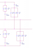
According to this site: http://www.smps.us/topologies.html, It is a DCM 2-switch flyback converter. However, I still have some doubts left. These components in the xxx.PNG file are strange. I don't know what the manufacturer wants to filter out. What are the reasons for putting these filters like this? Also, can the flyback topology act like an inverter instead of a dc-dc converter?
PS: Its specifications are 7.5kva rated input, 220Vac input voltage, 200A(dc) output current, and 100Vdc output voltage. According to the site, I think the welder is haphazardly designed because the DCM 2-switch flyback converter is not suitable for such a high power job. How about yours?
BlackMelon
I've just done reverse engineering on a burnt power converter PCB of the welder. I hope it'll be useful to those who need fixing the machine.
According to this site: http://www.smps.us/topologies.html, It is a DCM 2-switch flyback converter. However, I still have some doubts left. These components in the xxx.PNG file are strange. I don't know what the manufacturer wants to filter out. What are the reasons for putting these filters like this? Also, can the flyback topology act like an inverter instead of a dc-dc converter?
PS: Its specifications are 7.5kva rated input, 220Vac input voltage, 200A(dc) output current, and 100Vdc output voltage. According to the site, I think the welder is haphazardly designed because the DCM 2-switch flyback converter is not suitable for such a high power job. How about yours?
BlackMelon