Maker Pro
Maker Pro

A Little Delayed in Starting

I am starting a delay circuit for my guitar pedal, thanks to the nudge from VB.

I received the PT2399 Chip ( actually, I have 4 of them).

I am tempted to breadboard this first, but breadboarding. gets a little hairy- especially with all the wired and stuff. So, I am considering simply going to PCB.

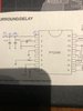
The schematic can be found on this thread:
#101

It is the project in the data sheet entitled Suround/Delay. Direct link to data sheet is here: http://www.princeton.com.tw/Portals/0/Product/PT2399_1.pdf
 
Thanks Bertus. While I can’t pretend I understand what each component does, the explanation on Peter Vis’ site provides a good idea of how things interrelate and play a role within the chip and in the circuit. I will read it again. It’s helpful. I did t know you can have a digital and analogue ground
 
I don’t have a socket for this chip. Is it possible to place two 8 pin op amp sockets together to act as a 16 pin socket?
 
Thanks Bertus. I just t=noticed, I thought I had 4 of these chips, but on closer look, it came with two chips and two sockets- so I should be good. Good to know for future reference though.
 
Hmm..my first question- this circuit seems to be powered by 5v. How do I achieve that if it is to be powered via a battery? It would be impractical to power it with a variable power supply.
 
https://www.electrosmash.com/pt2399-analysis
Further information of the PT2399 ... You shouldn't need much more than the datasheet example until you discover some of the quirks ... then the pin 6 strategies may come into play.
I have a dozen of these chips and sockets, as well as some multiplexers and kinky power management stuff.
This coupled to a head full of ideas ... this might be a fun thread
 
I would like to build this first and get it to work using the 5v from my variable supply, rather than get another chip right off the bat.
 

this guy seems to suggest that it will not work if built according to data sheet, but I have to think he’s wrong.
 
Last edited:

bertus

Moderator
Hello,

The datasheet shows that the normal oprating voltages are between 4.5 and 5.5 Volts.
PT2399_ratings.png
As said you can use a 7805 to regulate the voltage to 5 Volts.
One thing, the 7805 needs at least 7 Volts to be able to regulate.
A LDO regulator like the LD1117-50 needs about 6 Volts to be able to regulate.

Bertus
 

Attachments

  • LD1117XX.pdf
    973.5 KB · Views: 0
  • LM78XX_ni.pdf
    533.5 KB · Views: 0

this guy seems to suggest that it will not work if built according to data sheet, but I have to think he’s wrong.
Part right. Electrosmash has documented the chips quirks.
Pin 6 is the primary means to adjust clock speed ... AKA delay time.
Fast clock speeds (short delay times) cause it to choke if powered up while set to such speeds.
Since a reverb would be such an application ... the sucka gonna hang.
Longer, lush echos will be fine.
 
I have another question, and it is important for me to understand- although it may sound simple. Attached is a pic of the circuit we are building. You will note that I labeled (in pen), parts of the circuit with 1. 2. 3. and 4.

Here is my question:

On my PCB build, I have a Pin that I soldered in. The purpose of the PIN is to connect the + 5 volts to.

From a practical perspective, the positive leads from the 0.1uF cap and the 100uF cap, are both directly connected to the Pin that I mentioned above.

My question is this- will that way of connecting them work, or does the circuit require that point 2 be connected to point 1 , and that point 3 be connected to point 2.

In other words, does the 100uF cap have to connect to the 0.1uF cap before the 0.1uF cap gets connected to the 5V pin, or can the
positive leads from the 0.1uF cap and the 100uF caps both go to the 5V pin without first having to follow the sequence described above?

Part of me says that they both go to the same place, so what does it matter.

BUT,,,part of me says, maybe it matters the order they go there.

Thanks for any clarification you can provide.
 

Attachments

  • IMG_5306.jpg
    IMG_5306.jpg
    234.4 KB · Views: 4

bertus

Moderator
Hello,

The capacitors on the powersupply are decoupling capacitors.
They will provide a stable working of the chip, as the chip is a digital one and can create pulses on the power line.
You can read this thread on the AAC for more info:
Decoupling or Bypass Capacitors, Why?

Bertus
 
Hello,

The capacitors on the powersupply are decoupling capacitors.
They will provide a stable working of the chip, as the chip is a digital one and can create pulses on the power line.
You can read this thread on the AAC for more info:
Decoupling or Bypass Capacitors, Why?

Bertus

I sort of had a n idea as to their role, but the article made it clearer. However, my question is about whether the positive leads from both capacitors can be connected to the 5v pin at thr same time, ofr whether they need to be done in a certain. order (ie:the positive leads from the 0.1uF cap first and then and the 100uF cap_)

Maybe the article answered that question, but it escapes me. Are you saying that because they serve the decoupling purpose, that they have to individually run to the 5v pin?
 
Top