Hello,
A friend and myself are trying to build a brushless outrunner with a driver for a university project. The motor is being cut from sheet metal at the moment (my friends task), and I am building the driver. The motor has nine windings, so we thought we'd attempt a variable frequency 9-phase driver for it. I'm sure there is a good reason that this isn't commonly done but I don't know what that reason is yet, so we thought we'd find out.
The circuit I have designed is based around the superheterodyning of two 9-gate ring oscillators, and works as follows. A 9-gate ring oscillator (comprised of two 74HC14s) generates nine phases at about 6MHz. To slow this down, I have added resistors in between the gates and capacitors to ground on each gates input (1k, 100nF). This brings the frequency down to about 600HZ. A second, identical ring oscillator is running next to it. Every output of one ring oscillator goes to one of nine superheterodyne mixer circuits ( http://www.strangeapparatus.com/images/0ef9d08e2c4d897b93564c23e3001bfc_2qtt.jpg ). The other input of each mixer circuit is fed by one gate of the other ring oscillator. A simple envelope filter is used to further remove the high frequency component from the output of each mixer.
The voltage on one ring oscillator is varied slightly, changing its frequency. The mixer circuits gives the sum and difference of each waves frequency, and filters off the sum to give only the difference. When the oscillators are at the same frequency, there should be no output from the mixers (confirmed). If the difference in frequency of the two oscillators is 10Hz, then the output wave would be 10Hz (also confirmed). The result should be nine variable frequency phases.
The problem that I am having is that the phases aren't at ninths of a wave. I would have thought that (all being compared (or mixed) with one gate of the other oscillator), taking the signal from mixer one (connected to gate one of the oscillator) as my reference, signal two would be 40 degrees off, signal three would be 80 degrees off, signal four would be 120 degrees off etc...
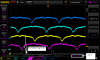
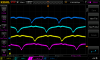
I have attached an oscilloscope output of the first four signals. The bottom trace is signal one, second to last is signal two etc.
I am worried that component tolerances, or variances in the propagation delays of the not gates in the oscillators are causing the problems. I've measured the phases of the signals going into the first few mixers (so coming out of the first few gates), some of which are the expected 40 degrees apart and some of which are closer to 180 degrees apart. I don't understand this, as surely the outputs of a 9-gate ring oscillator would all be one ninth of the frequency of the oscillator.
If it turns out that nine phase is a stupid idea, then the circuit can easily be scaled down to three phases, but I fear I would still have the same issues. And nine phase sounds cool!
Any help would be greatly appreciated.
Many thanks,
Tom
A friend and myself are trying to build a brushless outrunner with a driver for a university project. The motor is being cut from sheet metal at the moment (my friends task), and I am building the driver. The motor has nine windings, so we thought we'd attempt a variable frequency 9-phase driver for it. I'm sure there is a good reason that this isn't commonly done but I don't know what that reason is yet, so we thought we'd find out.
The circuit I have designed is based around the superheterodyning of two 9-gate ring oscillators, and works as follows. A 9-gate ring oscillator (comprised of two 74HC14s) generates nine phases at about 6MHz. To slow this down, I have added resistors in between the gates and capacitors to ground on each gates input (1k, 100nF). This brings the frequency down to about 600HZ. A second, identical ring oscillator is running next to it. Every output of one ring oscillator goes to one of nine superheterodyne mixer circuits ( http://www.strangeapparatus.com/images/0ef9d08e2c4d897b93564c23e3001bfc_2qtt.jpg ). The other input of each mixer circuit is fed by one gate of the other ring oscillator. A simple envelope filter is used to further remove the high frequency component from the output of each mixer.
The voltage on one ring oscillator is varied slightly, changing its frequency. The mixer circuits gives the sum and difference of each waves frequency, and filters off the sum to give only the difference. When the oscillators are at the same frequency, there should be no output from the mixers (confirmed). If the difference in frequency of the two oscillators is 10Hz, then the output wave would be 10Hz (also confirmed). The result should be nine variable frequency phases.
The problem that I am having is that the phases aren't at ninths of a wave. I would have thought that (all being compared (or mixed) with one gate of the other oscillator), taking the signal from mixer one (connected to gate one of the oscillator) as my reference, signal two would be 40 degrees off, signal three would be 80 degrees off, signal four would be 120 degrees off etc...
I have attached an oscilloscope output of the first four signals. The bottom trace is signal one, second to last is signal two etc.
I am worried that component tolerances, or variances in the propagation delays of the not gates in the oscillators are causing the problems. I've measured the phases of the signals going into the first few mixers (so coming out of the first few gates), some of which are the expected 40 degrees apart and some of which are closer to 180 degrees apart. I don't understand this, as surely the outputs of a 9-gate ring oscillator would all be one ninth of the frequency of the oscillator.
If it turns out that nine phase is a stupid idea, then the circuit can easily be scaled down to three phases, but I fear I would still have the same issues. And nine phase sounds cool!
Any help would be greatly appreciated.
Many thanks,
Tom
Attachments
Last edited:
")

![9phase2-1[1].png](/forums/data/attachments/22/22569-ec1af4a23c4bdd98d0c9080494f5eb91.jpg)
![9phase2-1[1].png](/forums/data/attachments/22/22570-ec1af4a23c4bdd98d0c9080494f5eb91.jpg)