Maker Pro
Maker Pro

555 Trigger

The sensor should give a pulse out when it detects a noise.
Does it?
What voltage are you using to power the sensor and the 555?
Note that the 555 takes a negative going signal to trigger it.
 
Last edited:
The datasheet of the Sound Impact Sensor says its output is active high. It already has a 555 timer on it.
Increase the 4.7k resistor to about 470k then after a noise triggers it, in 5 seconds its output will go low .
 
The sensor should give a pulse out when it detects a noise.
Does it?
What voltage are you using to power the sensor and the 555?
Note that the 555 takes a negative going signal to trigger it.
The sensor should give a pulse out when it detects a noise.
Does it?
What voltage are you using to power the sensor and the 555?
Note that the 555 takes a negative going signal to trigger it.
 
Thank you Audio Guru. For some reason I never looked at the actual chip on board, assuming that it was an amplifier. You are correct, that it is a 555.
 
The simple cheap Sound Detector Module was designed to use one electret microphone. It does not have a piezo disc and is not designed to drive one. The output of the module can be used to drive a piezo beeper that already has an oscillator in it.
 
The sellers at Fleabay use very poor translation. A passive piezo is a transducer but one that is powered from DC has an oscillator in it and its frequency listed. Some of the ebay ones have both passive and DC listed.
 
Sir . . . . . . . . B e e e e e e e e e g KIM . . . . . 98 . . .99 . . .100 !
LONG
see . . . .no TIME !
So I use your provided HOT link and it then sends me to Digi Key where I see a Parallax unit . . . .e w w w . . . it be velly-velly pricey . . . .9 + Amellican dollah . .. . . .Chinee onlee $1.32. . . . .but you waitee 3 week-1 monthee !

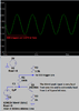
Their down load gives me this circuity . . . . now what I am seeing there is an Electret condenser microphone element and its internal FET circuitry is receiving its power via R5 and the VCC supply and its metalized mylar film capacitor diaphragm is receiving its polarizing voltages electrostatic charge from its adjunct mounted ferroelectric polar ring.
Then, DC isolated, audio output coupling is being made into the Q1 discrete audio preamp / DC level shifter via C1 poly/ cap.
( I see 3 vias on this side of the board so Q1 and some of its associative components must be on the other side of the board.)
As per your addition of another / other sensor mikes you might try the YELLOW mark up area and keep the duplicate / equivalent R5 and C1 elements, as is needed for each mike, close on board.
Then you remote in the mike (s) wiring . . . . . .( you did not specify distance ) . . . . but if being distant, their lines might need mesh shielded wire . . . . as per the 3rd mikes example.


SCHEMATIC MARK-UP . . . . .
upload_2021-11-30_2-47-3.png


SIDE THOUGHT . . . . from above
I can't quite fully "apprehend" the no-no need of non woven cloth aspect, which is assuredly JUST being relevant to the precise sound hole entry on the front center of the mike.
I can see the non use of a particular plastic family of threads. (Electrostatics)
I can see the avoidance of criss- cross, x to y plane interweaving of individual threads.
That then just leaves either a x-y precise micro- micro- spacing apart of all threads and then cross binding by adhesive or thermal bonding . . . .or else. . . .
The cloth is made in a porous matted construction . . .akin to thin black felt matting .


FINAL THOUGHT . . . . .
I see that you are still SPORTING your CHARTREUSE sl e e e e e e e e e e e e ng bikini . . . . .
MAN ! ! ! I'll bet that if you were to get that thing all wound up with your two "projectiles" inside, that you could hit the broadside center of distant barn . . . . . . ."SPLA T T T " . . ."SPLA T T T " . . .

73's de Edd . . . . .

WHYIZZITALWAYSDAT . . . .Clearly stated, concise instructions will consistently produce multiple interpretations.


.
 
Last edited:
The schematic recently posted:
1) No VCC voltage.
2) Mics in parallel load down their output levels.
3) The 1k emitter resistor on the no-part-number transistor reduces its voltage gain to be about 200 times too low.

The 555 in my simulation is not triggered when the input level is loud.
 

Attachments

  • bad mic preamp.png
    bad mic preamp.png
    21 KB · Views: 5
Peter, you do not have a condenser mic that needs to be biased with 48V. Instead you have an electret mic that has 48V permanently charged in its electret material.
Most electret mics draw 300uA to 500uA and need at least 2V across it. Then your 10k resistor powering it has a resistance too high
because 400uA in your 10k resistor uses 4V plus the 2V for the mic. The top of the waveform will have clipping.
The resistor should be 1V/400uA= 2.5k when the power supply is only 3V. I use 10k when the supply is 9V.

The darlington transistor will produce clipping of the waveform bottom because the value of the 1M bias resistor is too high for the 3V supply and the 10k collector resistor.
 
OK. Condenser mic AKA electret mic AKA electret condenser mic. The output waveform is severely clipped. It generates a spike. The ADC constantly reads the voltage on it and any change detected makes an output high. I never tried it but the spike could possibly trigger a 555. I don't understand where 48V comes from?
 
An old fashioned condenser mic uses an external 48V power supply to bias its fixed and audio-moving variable capacitor diaphragms.
A newer electret-condenser mic has the 48V permanently charged in its electret material.
The electret mic has a Jfet in it to convert the extremely high impedance of the capacitor diaphragms to a lower useable impedance.
The jfet needs to be powered through a resistor so that the Jfet has at least 2V across it and a current of 300uA to 500uA in it.

I explained before that your 3V supply is too low and/or the 10k resistor powering the Jfet in the mic is too high which causes the mic to clip the tops of the waveform. I asked you to replace the 10k resistor powering the mic to 2.2k or 2.7k.

Your MPSA13 should have its collector idling at about 2VDC then its collector current in the 10k volume control is1V/10k= 100uA. The base voltage will be about 1.2V and its DC gain will be maybe 10000 then its base current will be 10nA.
With a collector voltage of 2V and a base voltage of 1.2V then the bias resistor with 2V - 1.2V= 0.8V across it and 10nA in it which would be a resistance of 0.8V/10nA= 80M ohms. Therefore the 1M value of it is way too low causing the MPSA13 to be severely clipping the bottoms of the waveform.

Why did you use the MPSA13 darlington when an ordinary two-transistors mic preamp should ne used? A single transistor will produce too much distortion when its voltage gain is high enough to be a mic preamp.

Please measure and report the DC voltage of the mic and the collector voltage of the MPSA13 darlington.
 
I checked the circuit. The schematic and parts values above are accurate. As I mentioned, this is not a preamp per se, it is only sending a spike to an ADC. This circuit has been in use for 10 years and we never had a problem with it. You can breadboard it and try it in "real life" with a scope. It even works with a ceramic mic. Just remove the 10K mic resistor.
 
Top