Maker Pro
Maker Pro

555 timer circuit help?

I want to make this basic circuit but with a pot to get an adjustable frequency


How can I modify this to use a pot??

I tried what I thought would work, but it didn't function from what I could tell.
 
I want to make this basic circuit but with a pot to get an adjustable frequency


How can I modify this to use a pot??

I tried what I thought would work, but it didn't function from what I could tell.
Awesome. Good to see someone trying to pick something up like this.
Show us a circuit diagram or sketch of what you tried, let's point you in the right direction.
 
Last edited:
The heart of it so to speak, is the timing capacitor/potentiometer..

What do you have in mind for it? (The 555 is the swiss army knife of the electronic world)
 
If you use android, download electrodroid, very handy!

It's very comprehensive, it's saved my butt a few times :)
 

Attachments

  • Screenshot_2016-02-28-10-50-50.png
    Screenshot_2016-02-28-10-50-50.png
    325.1 KB · Views: 185
  • Screenshot_2016-02-28-10-50-57.png
    Screenshot_2016-02-28-10-50-57.png
    294.5 KB · Views: 137
  • Screenshot_2016-02-28-10-51-09.png
    Screenshot_2016-02-28-10-51-09.png
    212.5 KB · Views: 112
  • Screenshot_2016-02-28-10-51-22.png
    Screenshot_2016-02-28-10-51-22.png
    309.5 KB · Views: 106
Ok, so I got all my parts in the mail for this, I got a few extras of each cause why not, and my pots are 200 instead of 250 k, but I figure that wont matter to much. But, in all honesty, I'm having trouble understanding what to hook where in respect to the 555 times since the pic is quite a bit blurry. Whats the best way to figure out how to lay down whats in the schematic on a breadboard?

This is the circuit that I am using by the way.
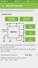
http://www.electronicecircuits.com/electronic-circuits/555-variable-frequency-square-wave-generator

EDIT: So I actually changed my plan and just decided to use this more simple circuit.

qBHceT1.jpg


If it is even applicable to what I am trying to accomplish. So I wired it up, and here are some of the pics of what I have so far, I'm sure there are errors so please let me know.

QSgzSNq.jpg


yUMsy3G.jpg


TMjR0II.jpg


The power is the line going to 8. And the ground is not in in these photos.


Basically is all I'm trying to do is produce a lower range frequency(square or sine), if they still made radio coils I would probably just use that and a capacitor lol.
 
Last edited:
What is the value of R1 (from pin 8 to pin 7)?
What is the value of the timing capacitor?

What are you using to look at the output? If you want an LED to blink slowly enough to be visible, the capacitor probably will have to be larger.

ak
 
I see several mistakes....

I see only 1 resistor, you're missing 1, you also have a low ceramic value prob under 1uf, no problem though, with large enough resistance, also you made the curcuit difficult to build, use the rails at the top and bottom (if you have hookup wire)

Lastly although not an issue, you appear to be using 1/2watt resistors for a 1/4watt job :)
 
Think you need to look a little closer at the operation of the 555 and what resistor and capacitor values values are recommended as minimum.
Talking Electronics have a good free online book on 555's and many circuits available with circuit explanations.
R1 looks like 20R to me but could be wrong.
Wiring twisted into a pot terminal like you have will cause intermittent operation.
A pot used in this way could at some time be turned down to zero, not a good idea.
If you must use a pot, use a minimum value resistor in series to avoid the problem.
 
Top