Maker Pro
Maker Pro

2W Voltage amplifier help

Greetings,
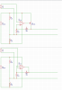
I've designed two circuits but tested only one of them (see attached pic). My question is, will the other one - the one with the transistor - work(?)
I need a circuit that will amplify an input signal which varies from 0V to 1V.
The output should scale linearly from 0V to 5VDC.
The input signal can supply enough current to drive a 50ohm resistor at 1V, but current-limits at ~1.3V.
The output needs to supply 5V across 50ohms.
I have a 30VDC power supply (from deceased printer).
I would like to build the circuit with parts available at FRYs.

Any help is appreciated!
 

Attachments

  • VoltageAmp.png
    VoltageAmp.png
    26.3 KB · Views: 146
Welcome to EP.
1. I can't see any 2W in your design or requirements.
2. 50ohm signals are normally AC and not DC,you need to clear that point.
Find out what is the signal you need to amplify and it's frequency range as well.
 
A couple of things.

5 V across 50 ohms is 0.5 W, not 2 W,

The output current return is through R2 (which is shorted ont on your drawing), so the output power will be nowhere near 0.5 W, let alone 2 W.

For the circuit to work the way you want, the system ground needs to be a direct connection to a power supply terminal, such as the center point between two 9 V batteries. R1 and R2 are ok to set the signal ground (if you add decoupling capacitors), but not the power GND.

The circuit has a very unsymmetrical output impedance. It can source lotsa current with the transistor to pull the output voltage up, but there is no corresponding low impedance path to pull the output voltage down.

ak
 
Welcome to EP.
1. I can't see any 2W in your design or requirements.
2. 50ohm signals are normally AC and not DC,you need to clear that point.
Find out what is the signal you need to amplify and it's frequency range as well.

Thanks for the reply.
The 50 ohm signal is the control input to an acousto-optic modulator. The MFR calls it a "TTL" input and, in fact, it switches the AOM's output on and off (when ON a 10MHz signal is sent to a crystal). In our application the on/off switching won't happen faster than about 10KHz. Eventually this same circuit will drive a similar AOM with an analog input (50ohm); there, the amplitude of AOM's 10MHz output is modulated by my circuit's output.

Re. 2W: I'd like this circuit to handle all/most different models of AOM's we may encounter. I think 5V(50ohms) is the maximum voltage/power we'll ever need to supply, but it would be nice if I could drive 10V/50ohms, just in case, Still, that will require different parts and I have trouble finding the parts I want at NTE.

Do you think the NTE383 circuit will work (at 5V/50ohm)?

What's the off-the-shelf name of a product to do this kind of conditioning?
 
A couple of things.

5 V across 50 ohms is 0.5 W, not 2 W,

The output current return is through R2 (which is shorted ont on your drawing), so the output power will be nowhere near 0.5 W, let alone 2 W.

For the circuit to work the way you want, the system ground needs to be a direct connection to a power supply terminal, such as the center point between two 9 V batteries. R1 and R2 are ok to set the signal ground (if you add decoupling capacitors), but not the power GND.

The circuit has a very unsymmetrical output impedance. It can source lotsa current with the transistor to pull the output voltage up, but there is no corresponding low impedance path to pull the output voltage down.

ak

I may be able to design this around a different power-supply - say +/- 12V.
Probably there's a product that will do this.
 
There are thousands of circuits and products that will amplify an analog signal when powered from +/-12 V. A clean 10 kHz square wave or pulse requires a signal bandwidth much greater that the standard audio 20 kHz. Depending on how close to 0V the output must be, you might be able to get away with a single-supply circuit. A block diagram of the system components, signal levels, and which part you are talking about would help greatly.

ak
Hi AK,
In case it helps, the input signal is output from a motion-controller. It takes the controller 100us or more to change the signal from 0 to 1V. This analog value represents a desired laser intensity - %0 to %100. The % laser intensity varies with the specific application but may stay constant during entire motion. Another application may require "rapid" position-dependent intensity changes. Even a "low" intensity (%1) may have an effect, so I think the circuit's output must go to zero.

Today I went to an electronics store and looked at pages of parts and kits I could order - including something called a "single channel audio amplifier". I don't know how well these devices might be suited to my application - do they (typically) "tolerate" a DC input? Do they have a problem driving 0V? I'll probably order one, online, from Digi-Key later today. Please let me know if you have any recommendations!

Thanks.
 
no and yes. As a blanket statement, audio devices will not be suitable for your project. A small percentage are DC coupled, but they use a low frequency servo amplifier to achieve this, and it assumes that the average value of the input waveform is zero. So, audio = bad.

a 100 us risetime into 50 ohms is pretty easy to achieve. What about the return to zero? Must it be equally fast? If yes, then I think we're back to bipolar power supplies. If no, then your first schematic with the external PNP transistor might work with a little tweaking.

Summary Analog pulse amplifier parameters:

Input voltage range: 0.0 V to 1.0 V
Input risetime: 100 us, 0% to 100%
Input falltime: ??? <-----

Output voltage range: 0.0 V to 10.0 V
Peak output current: 0.20 A
Output risetime: ??? <-----
Output falltime: ??? <-----
Output source impedance: ??? <-----

Pulse width, duty cycle ratio, min/max up time, min/max down time, etc?

ak
 
(snip)
Must it be equally fast? If yes, then I think we're back to bipolar power supplies.
(snip)
Summary Analog pulse amplifier parameters:

Input voltage range: 0.0 V to 1.0 V
Input risetime: 100 us, 0% to 100%
Input falltime: ??? <-----

Output voltage range: 0.0 V to 10.0 V
Peak output current: 0.20 A
Output risetime: ??? <-----
Output falltime: ??? <-----
Output source impedance: ??? <-----

Pulse width, duty cycle ratio, min/max up time, min/max down time, etc?
ak
Hi AK,
Input falltime = rise time.
Output must follow input, so output risetime = falltime = 100us (minimum)
There should be as little latency between input and output response as is practical - 100ns should be more than fast enough.
Re: Output source impedance:
Well, there is no spec - it's whatever works best with the laser-modulation device. Current device, an AOM, has a 50ohm pull-down on this signal, but another AOM, EOM, or ? may not have 50ohm pull-down. I guess it's right to say we may connect the circuit's output to a "high impedance" input. With such a slow risetime/fall time, I wasn't worried (much) about impedance matching.

I don't think "Pulse width, duty cycle ratio," terms are applicable here. There are no "pulses".
I'll plan to redesign the circuit to run on 12VDC - adding an IC to generate negative 12V.

Continuing thanks for the help. :)
 
Is the 1 V signal continually varying between 0 V and 1 V, and 10,000 V/s is the maximum rate of change as it varies, or does it go up to 1 V, sit there for a while, then go back down to 0 V? What goes up...

Think about a 50 ohm output resistor for source-terminating a coax cable. It doubles the driver headroom requirement, but could have a measurable effect in reducing bumps and wiggles caused by reflections. How long is the connecting cable?

ak

Hi AK,
A few posts back I mentioned that this signal needs the ability to do both: sit at a level or vary quickly between arbitrary levels - 10,000V/s is a reasonable maximum requirement.

Since you have suggested it, I'll plan on using a 50ohm source termination resistor. This is all new/experimental, so there's no existing cable. Comfortable cable lengths will probably run around 10 or 12 feet.

Cheers.
 
Can you please post the datasheet of the AOM with the analog input.
Is it's modulation PAM?

Hi dorke,
Sorry, I don't know what PAM means.
The mfr is Gooch & Housego but (I'm home and) don't remember the RF controller model#. I'll reply with datasheet tomorrow.

Cheers.
 
PAM =Pulse Amplitude Modulation
Hi dorke,
The datasheet for RF controller w/analog input is here: "http://goochandhousego.com/wp-content/uploads/2013/12/97-02910-18-50-Rev-A.pdf". I think it's simply modulating amplitude - no "pulses" involved.

NOTE: I'm spending a lot of time searching for parts - is there an IC that will make -12VDC from +12VDC? Is it necessary to drive the Vs- input with a symmetrical voltage as Vs+? For instance, could I drive Vs+/Vs- with +12V/-5V - considering my the circuit's output NEVER needs-to/should go below 0V.(?)
 
Last edited:
is there an IC that will make -12VDC from +12VDC?
With a 50 ohm output resistor, 50 ohm load, and 10 V at the load, that's +20 V @ 200 mA worst case output, requiring a 24 V positive power source. There are many small DC/DC converter modules that will turn +24 V into -5 V for the negative rail.

If you back off the output requirements to a 10 V peak, then there are charge pump converter chips that will do this, or off the shelf small inverting buck regulators, or even a 555 driving a charge pump.
could I drive Vs+/Vs- with +12V/-5V - considering my the circuit's output NEVER needs-to/should go below 0V.(?)
Yes.

ak
 
Top