Maker Pro
Maker Pro

18dec to 5bin converter

Hey guys, I've successfully designed a converter from 0-18dec to 0-11111bin using only diodes and resistors (cheap!) but I was wondering if there is a more efficient way of doing this?

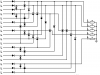
In the attached schematic, it requires 38 diodes and 5 resistors!

Imagine the L's (logic input) to the left of the schematic to be low impedance voltage sources at 5v and the L's at the right (logic output) to be very high impedance (input of non-inverting schmitt trigger), worst case scenario will be 2 diode drops into 1Meg, in 100% efficient diode conditions, maximum current will be 5uA, therefore, using standard 1n4148 diodes, gonna expect a maximum voltage drop over 2 diodes to be around 1.2v (minimum stated value on the datasheet is 5mA). This is within specification of high being >(+V/2) and low being <(+V/2)

But to the point, is there any more efficient ways, chips that can do this for me?

Thanks, Harris
 

Attachments

  • 18dec to bin converter.png
    18dec to bin converter.png
    21.7 KB · Views: 116
Depends on what you mean by efficient. Speed, power, component count, board area, which is it?

Bob
 
Preferable component count and board area, are there any better ways to do this than just using steering diodes? Speed is not essential.
 
A single 28-40ish pin micro, overkill in MANY ways but still cheap (about $1) and very low board real estate if you go with a small SMD package...
 
Well the thing is, i'm using it to input 18 switches into an arduino using as little pins as possible, i considered using an 18 part potential divider and analog reading but doing a direct port read is much more time efficient than analogread so unfortunately, using an extra IC seems a tad pointless! Any other suggestions?
 
Well, that is a different problem than you originally posted. Your circuit will not work If more than one switch in on.

Are you talking about 18 switches, which can all be in either state at any time? Or are you talking about a keypad where you expect one key to be pressed at a time?

If the latter, you can arrange them in a 4x5 matrix and you would need 9 pins on the micro to read them.

Bob
 
1 Switch at a time is no problem! Also, if they're not high, they will be in a high impedance state (unconnected to either rail). Getting significant data out of switch combinations is not a big deal, I just need to know which switch is on at what time. This is where I will just do a direct port read of the 5 bits and at any instantaneous time, get the result of which of the 18 switches is high.
Cheers!
 
using an extra IC seems a tad pointless!

Why? You listed your primary concerns as board space and parts count, based on that criteria your original solution is the one that is a tad pointless... There is always a give and take on all solutions weigh your options based on your criteria, a matrix input as Bob suggested is generally the best choice...
 
Last edited:
Very true! Apologies for my ignorance. I shall be more specific next time I post questions.

What I should ask then is:
Based on my above diagram, can I achieve the same results using less components BUT sticking to discreet components?

Sorry about that one guys!
 

(*steve*)

¡sǝpodᴉʇuɐ ǝɥʇ ɹɐǝɥd
Moderator
Based on my above diagram, can I achieve the same results using less components BUT sticking to discreet components?

Yes, you have 11 diodes you don't need. (All the ones pointing from left to right in the first "column".
 
Top