A.l.w.a.y.s post a schematic.
This is one of the things that is not intuitively obvious to a beginner, because it involves the consequences of how a battery actually functions, and it appears to the rest of the circuit.
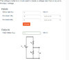
My GUESS is that you are trying to step down the 9 V to 1.5 V with a two-resistor voltage divider. If so, the problem is output impedance, or Thevenin equivalent resistance.
Assuming you are connecting the bulb across the 2K resistor, that means the two are in parallel. I measured a 1.5 V penlight bulb, and its cold resistance is around 1.0 ohm. So the equivalent resistance at the bottom of your divider isn't 2,000 ohms, it is 1 ohm. If you re-calculate the output voltage, you will see it is very low.
That is a quickie estimate. There is a right way to put the impedance of a voltage divider in context with the load attached, called the Thevenin equivalent resistance. for your circuit; it goes like this:
The battery has a (theoretically) zero ohm output impedance, and between its two terminals are two resistors in series. The *effective* impedance at the center point isn't 10K or 2 K, it is 10K and 2K in parallel, or 1.67 K. This is because the zero ohm output impedance of the battery effectively "shorts together" the 10K and 2K resistor ends. The voltage at the center point is 1.5 V as you've calculated. So what the light bulb "sees" as its power source is a 1.5 V battery in series with a 1.67K resistor. That 1.67K equivalent resistance in series with a 1 ohm bulb makes for a huge attenuator (0.06%), which is why the bulb doesn't light.
This is a bit math-heavy, but covers the topic:
https://en.wikipedia.org/wiki/Thevenin_circuit
A.l.w.a.y.s post a schematic.
ak