Learn how you can connect the micro:bit, an ARM-based embedded system, to an ESP8266 NodeMCU!
The ESP8266 Wi-Fi microcontroller-based NodeMCU can be used in a variety of monitoring and control applications including electronic temperature measurements, sound level detection, gesture detection, and motor driver controls.
To extend the ESP8266 control application’s capabilities, a traditional discrete LED indicator used for the “hello world” code demonstration can be upgraded with a micro:bit.
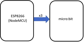
The micro:bit has a 5x5 array of discrete programmable LEDs that allow for the creation and display of a multitude of messages and graphics. This hands-on tutorial shows you how to wire an ESP8266 WiFi microcontroller to a micro:bit using three wires.
Figure 1. Block diagram of a basic 3-wire interface of an ESP8266 NodeMCU to micro:bit
With this three-wire scheme, you can create a programmable emoji device that we’ll cover in this tutorial as well.
Required Hardware
- ESP8266 Node MCU Development Board: U1
- micro:bit: U2
- Solderless breadboard
- Small alligator clips
The Main Power Distribution Scheme
The overall objective in wiring the ESP8266 NodeMCU to the micro:bit is to use one power supply.
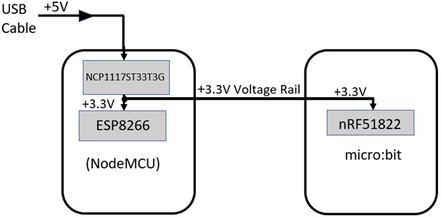
The NodeMCU and the micro:bit are both powered by a 3.3VDC voltage source obtained from a USB cable. The USB cable provides +5VDC to the embedded boards which steps down the main source voltage to +3.3VDC. Therefore, the main power distribution scheme is to allow the NodeMCU to actively power the micro:bit. To accomplish this power distribution scheme, we must establish a power rail.
Figure 2. Establishing a power distribution rail.
As illustrated in Figure 2, the USB cable provides a +5VDC voltage source. The NodeMCU‘s voltage regulator will step down the USB cable’s +5VDC voltage to +3.3VDC. This +3.3VDC source is available to use to power the micro:bit device.
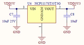
The NodeMCU’s voltage regulator is an ON Semiconductor NCP1117 series electronic component. The NCP1117 provides a constant voltage of +3.3VDC with a maximum sourcing current of 1A. The working sourcing current at 3+3VDC is 800mA. This sourcing current can operate the micro:bit satisfactorily.
The partial circuit schematic diagram from the NodeMCU documentation is shown in Figure 3.
Figure 3. The ESP8266 NodeMCU +3.3VDC voltage regulator.
With an understanding of the power distribution scheme, you are now ready to wire the ESP8266-based NodeMCU to the micro:bit.
How to Wire the NodeMCU to a micro:bit
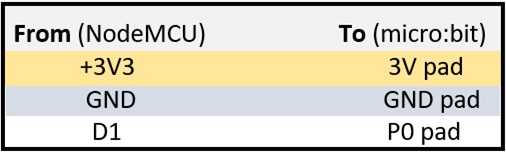
Wiring the NodeMCU to a micro:bit requires a solderless breadboard and three alligator clips. Insert the NodeMCU into the solderless breadboard. Next, insert the alligator clips using the following color code scheme:
- A red alligator clip inserted into the +3V3 pin cavity (hole) on the solderless breadboard.
- A black alligator clip inserted into the GND pin cavity on the solderless breadboard.
- A blue alligator clip inserted into the D1 pin cavity on the solderless breadboard.
Attach the color alligator clips from the solderless breadboard to the micro:bit using the following electrical connections table.
Table 1. Alligator Clip Electrical Connections
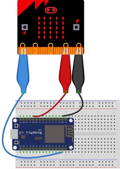
Figure 4 shows the complete Fritzing diagram of the electrical wiring between the NodeMCU to the micro:bit.
Figure 4. The electrical wiring diagram for the ESP8266 to micro:bit pin connections.
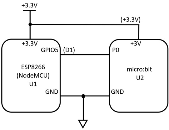
As an additional reference, you may also use the electronic circuit schematic diagram shown in Figure 5 to wire the two embedded platform devices together.
Figure 5. The ESP8266 based NodeMCU to micro:bit electronic circuit schematic diagram.
After wiring the two embedded devices together, we can program the NodeMCU and the micro:bit as the final step.
Software for the ESP8266 and the micro:bit
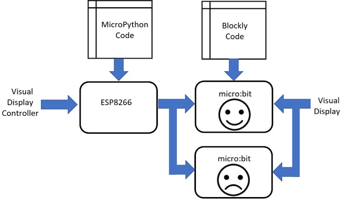
The overall learning goal of this tutorial is to create a programmable emoji. The concept of the programmable emoji is to display two images — happy and sad faces — on the micro:bit. The happy face displays when the micro:bit receives a binary 1 value from the NodeMCU. The sad face displays when the micro:bit receives a binary 0 value. Figure 6 illustrates the programmable emoji concept.
Figure 6. Happy and sad face displays: the programmable emoji concept block diagram.
Programmable Emoji MicroPython Code
# A Programmable Emoji
import time
from machine import Pin
led=Pin(5, Pin.OUT)

while True:
  led.value(1) # Display a happy face
  time.sleep(0.2)
  led.value(0) # Display a sad face
  time.sleep(0.2)
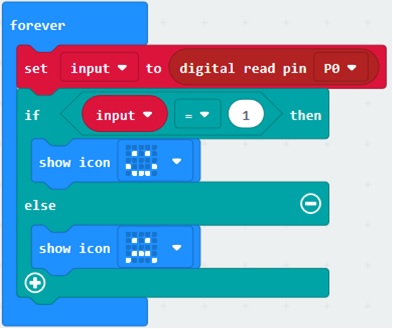
The micro:bit code was created using the Microsoft Makecode IDE. You can create the code using Google’s Blockly Code as shown in Figure 7.
Figure 7. The micro:bit Programmable emoji Blockly code.
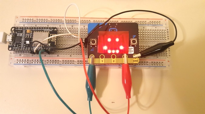
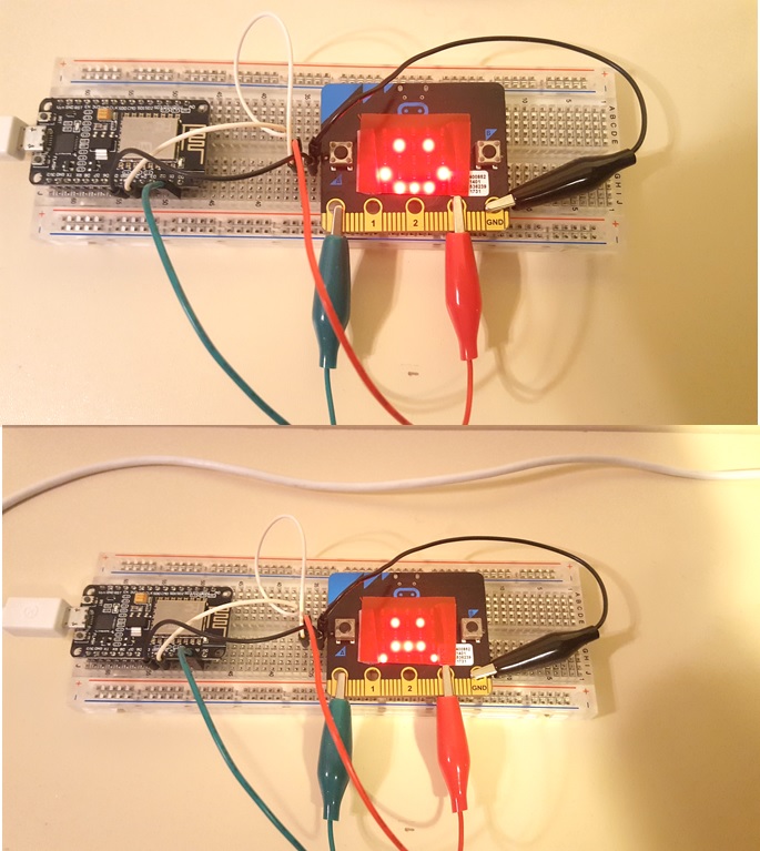
With the Blockly and MicroPython code uploaded to the micro:bit and the NodeMCU development board, the image should toggle between the happy and sad faces. Figure 8 shows the code actively running on the micro:bit.
Figure 8. A functional programmable emoji.
As a challenge, try modifying the flash rate and the image displayed on the micro:bit. Happy coding!