Learn how to use the ESP8266 to give your Arduino or Raspberry Pi boards wireless capabilities.
Many projects require some kind of communication between different devices and the goal of this article is to introduce you to the basics of connecting a microcontroller to the internet wirelessly by utilizing an ESP8266 breakout board.
Longer code examples for this tutorial are available for download at the end of the article.
Testing the Wireless Adapter With Arduino
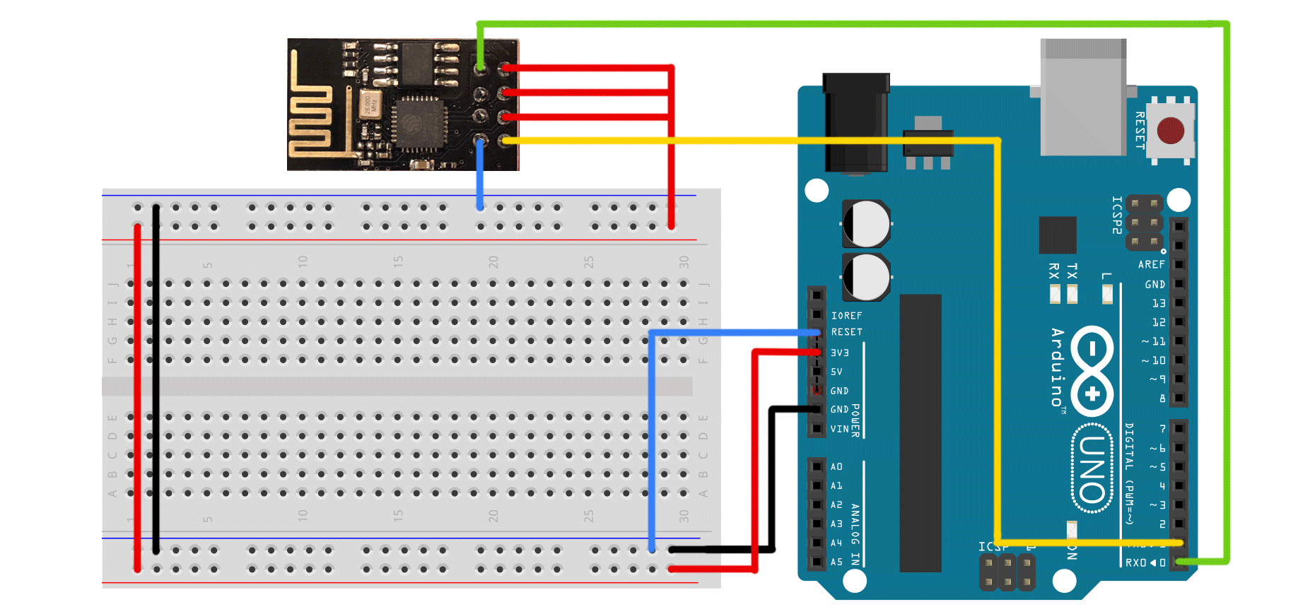
The bootloader of some Arduinos can be disabled by connecting the reset pin to ground. This will allow you to directly communicate with a device (like the ESP8266) that is connected to the board’s serial port:
Many different breakout boards are available so I can’t give you a general hookup guide for each one. Some require additional resistors and capacitors to work safely. Consult your board’s documentation for further information!
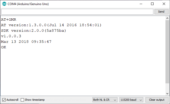
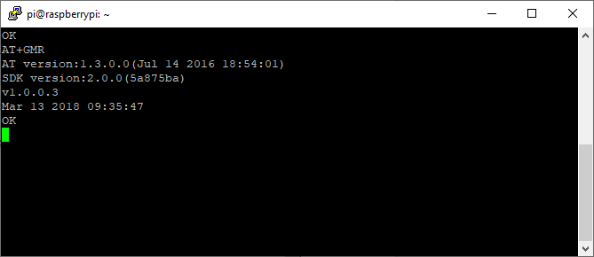
You can then start the Arduino IDE and open a new serial monitor. Set the baud rate to 115200 (some older adapters might use 9600) and the line ending to “Both NL & CR”. Then type “AT+GMR” in the input field and hit enter. The response should look like this:
Understanding AT Commands
These are used to connect the adapter to a network, send and receive data and disconnect the device. It only accepts a relatively small number of instructions but some devices, like cellular adapters, can interpret additional commands for making phone calls, etc.
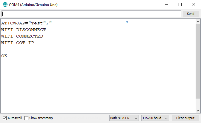
Anyway, let’s start with establishing a Wi-Fi connection:
AT+CWJAP="SSID","password"
Replace SSID with your network’s name and type your password. You should receive an answer similar to mine:
If you get an error, you can check what mode the device is in by using:
If it’s in mode two, change it to one or three and try connecting to your local network again:
Setting it to mode one will make the adapter behave like a client device. Mode two is for servers and mode three is the dual mode.
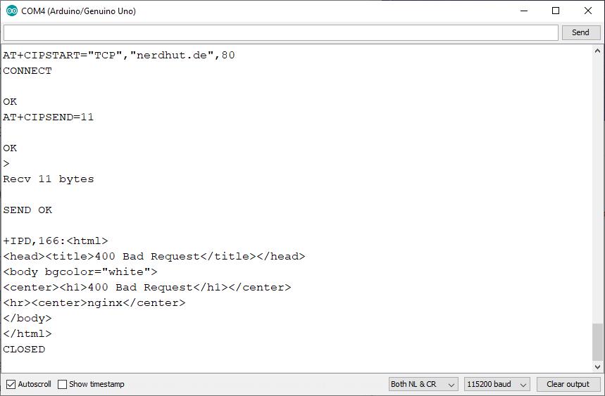
Upon connecting, you can communicate with a server:
AT+CIPSTART=”TCP”, “server”, port
Will establish a TCP connection to the server on a specific port. The server itself can be a hostname or an IP-Address. The second command will attempt to submit a specific number of bytes.
AT+CIPSEND=number_of_bytes
You can then enter a message in the serial monitor that’ll be sent to the server. The response gets printed to the console.
This was a short summary of the most important commands. Refer to this page for a full list of supported instructions.
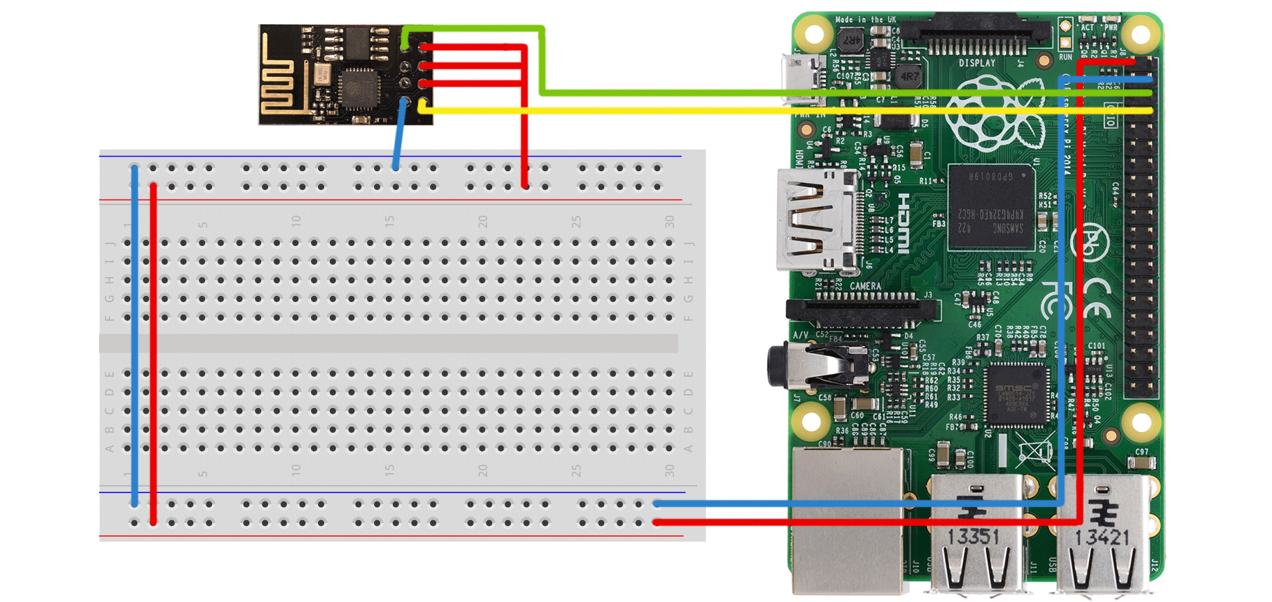
Using the ESP8266 With a Raspberry Pi
Note that newer models of the Pi have a built-in wireless interface and there are more convenient options available, like WIFI dongles. The image above illustrates the wiring for a Raspberry Pi B+. Just make sure to connect the ESP8266’s TX to RX on the Pi and vice-versa.
To test the module, boot up your Raspberry Pi and use the screen command:
sudo screen /dev/serial0 115200
Enter any of the supported AT instructions and hit the enter key followed by Ctrl + J (for the additional carriage return):
Interfacing the Adapter from Arduino Code
This works in exactly the same way as the manual test from above. But before you begin, make sure to disconnect the Arduino’s reset pin from GND and connect the module’s RX and TX to pin eleven and ten on the Arduino. The following sketch sends a few AT commands:
Please insert the ESP8266-Arduino-test-program.txt here
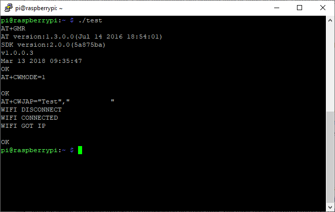
Interfacing the Adapter With Linux and C
Because the Pi is running a Linux system, the adapter is represented as a single file that can be written to and read from using standard operations. The following example initializes the adapter and connects it to a network:
Please insert the ESP8266-test-program.txt here
Running the code should give you the following output:
The ESP8266 can easily be interfaced by any device that supports a serial connection.
However, the Arduino Software Serial library can be a bit slow, so you should try to directly connect the adapter to the Arduino’s serial interface in a finished project (and remove the serial debug output) to ensure proper readouts.
The Raspberry Pi doesn’t suffer from these issues because the hardware is accessed directly.
More Information on the ESP8266