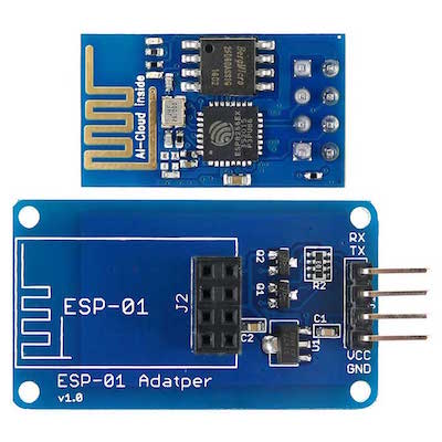
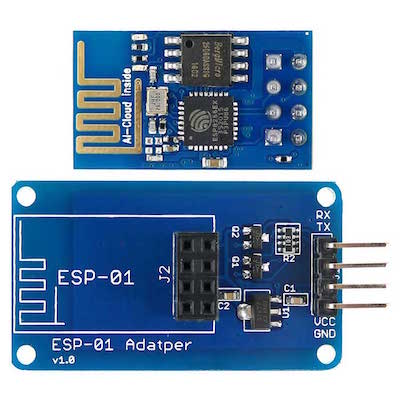
How to set up and configure the ESP-01 Wi-Fi module so you can connect your project to the internet.
The ESP8266 is a great tool for enabling your project to access the internet. The ESP8266 is a very low-cost module that comes pre-programmed with an AT command set firmware, meaning you can simply hook this up to your Arduino device and get about as much Wi-Fi-ability as a WiFi Shield offers. This module has powerful onboard processing and storage capability that allows it to be integrated with the sensors and other application through its GPIOs.
In this tutorial, we'll show you how to get started with the ESP-01 Wi-Fi module, configure it, and verify that there is communication established between the module and another device without using an FTDI chip.
Connecting the ESP8266
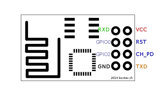
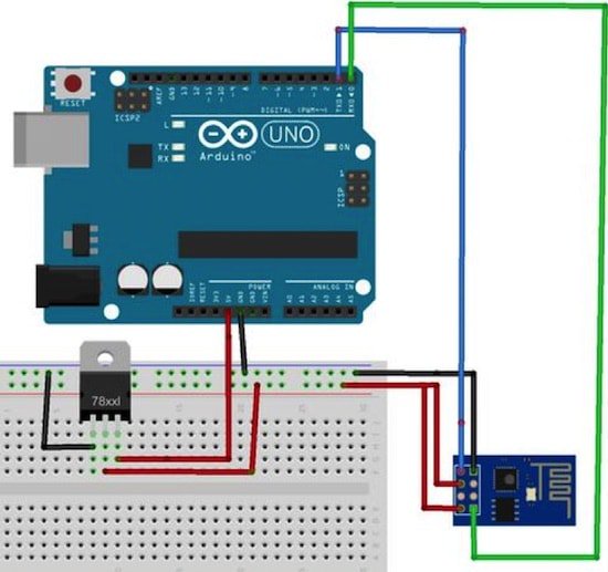
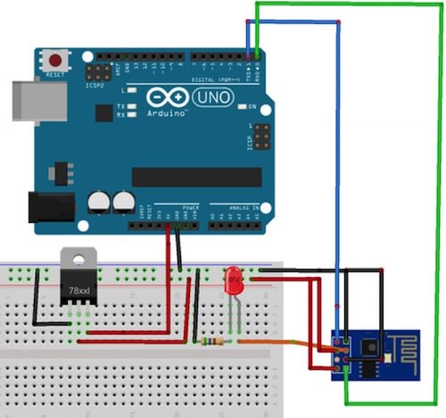
Now, connect the ESP8266 using these instructions:
- VCC will be connected to the 3.3V power supply.
- GPIO0 and GPIO2 are general purpose digital ports. GPIO0 also controls the module mode (programming or normal operation). In our case (normal operation), it shall be connected to 3.3V (high). GPIO2 is not used in this example.
- Rx: Goes to Arduino pin0 (But needs a voltage adjusting)
- CH_PD: Chip enable. Keep it on high (3.3V) for normal operation
- RST: Reset. Keep it on high (3.3V) for normal operation. Put it on 0V to reset the chip.
- GND is ground.
- Tx: Goes to Arduino pin1.
ESP8266 modes: (Setup continued)
Open the serial monitor and change the baud rate to 115200 and choose NL and CR (new line and carriage return) from the drop-down menu. Type AT on the serial monitor, and you will see OK as theresponse. If you see garbage value on the screen, try resetting the module or checking your baud rate. Make sure the NL and CR option is set. Moreover, the ESP8266 module has three operational modes:
1. Access Point (AP) — In AP, the Wi-Fi module acts as a Wi-Fi network, or access point (hence the name). It allows other devices to connect to it. And establishes a two-way communication between the ESP8266 and the device that is connected to it via Wi-Fi.
2. Station (STA) — In STA mode, the ESP-01 can connect to an AP (access point) such as the Wi-Fi network from your house. This allows any device connected to that network to communicate with the module.
3. Both — In this mode ESP-01 act as both an AP as well as in STA mode. Refer to the following site for more ESP8266 AT commands.
Installing the ESP8266 Platform
First, the Arduino environment has to be set up to make it compatible with the ESP-01 module. It is required to have Arduino version 1.6.4 or higher in order to install the ESP8266’s platform packages.
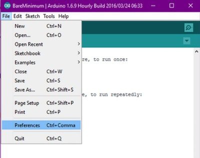
1. Open the preferences window from the Arduino IDE. Go to File >Preferences
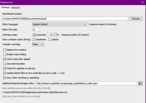
2. Enter http://arduino.esp8266.com/stable/package_esp8266com_index.json into Additional Board Manager URLs field and click the “OK” button
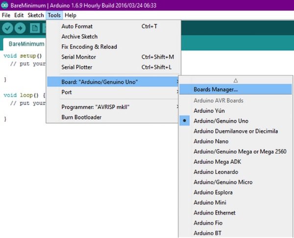
3. Open boards manager. Go to: Tools > Board > Boards Manager…
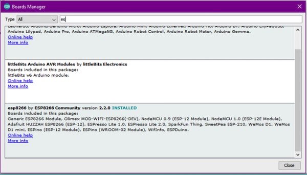
4. Scroll down, select the ESP8266 board menu and install “esp8266 platform”.
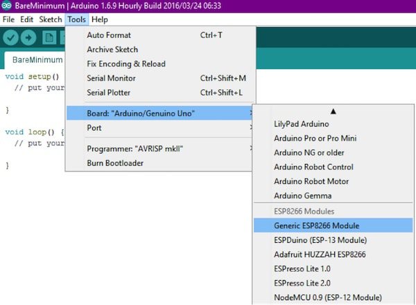
5. Choose your ESP8266 board from Tools > Board > Generic ESP8266 Module
Controlling the Input and Output
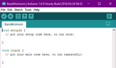
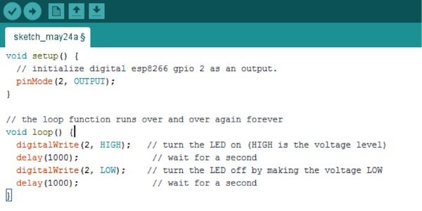
In Arduino IDE, go to "examples" and open the blink program. Change the pin number to 2 from 13, since there are only two GPIOb pins for the ESP8266 (GPIO0 and GPIO2). NOTE: Make sure that GPIO0 is grounded while uploading the code.
Connect the ESP-01 module as per the diagram above, then upload the sketch shown below and watch the magic!
Feedback and questions are welcome! Thanks for reading.
