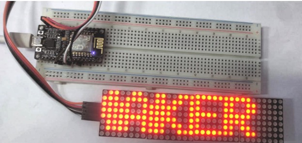
Learn how to use a NodeMCU ESP8266 to display custom messages on an LED dot matrix display.
Driving LEDs can be done in a variety of ways: by using shift registers, multiplexers, or driver ICs. I think that going the dedicated LED driver IC route will make your life much easier.
This project uses an LED dot matrix based on the MAX7219 from Maxim, which is an 8-bit LED display driver chip. These chips are designed to control up to 8-digit 7-segment digital LED displays, bar graph displays, or 8x8 LED dot matrix displays. Arduino IDE provides a library called Matrix with sample code written for the MAX7219 chip.
Along with the MAX7219, we will use an ESP8266 and a dot matrix display to display messages sent over the local Wi-Fi network. The code can also be modified to allow these messages to be sent through the internet using different APIs.
Programming the ESP8266 With Arduino IDE
As Arduino.cc began to develop new MCU boards based on non-AVR processors (such as ARM / SAM MCU), they needed to modify the Arduino IDE in order to support the spare tool. Doing so allows the Arduino C / C++ code to be compiled into these new processors.
They achieved this by introducing a board manager and a SAM core. When we talk about the "core", it is a collection of software components required by the board manager and Arduino IDE to compile the Arduino C / C++ source files into the machine language of the target MCU. Some creative ESP8266 supporters have developed the Arduino core for the ESP8266 Wi-Fi SoC, which can be found on the GitHub ESP8266 core web page.
This is commonly referred to as the "ESP8266 core for the Arduino IDE", which has become one of the leading software development platforms for various ESP8266-based modules and development boards (including NodeMCU).
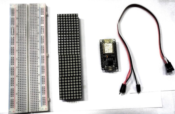
Required Hardware
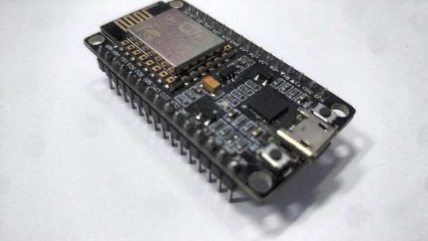
- NodeMCU ESP8266
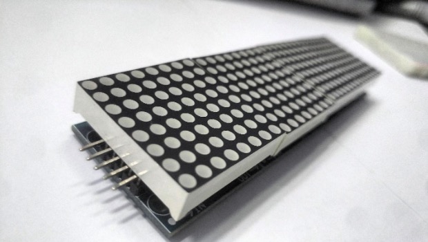
- MAX7219 dot matrix
- Jumper Wires
- Breadboard (optional)
Front view of the MAX7219.
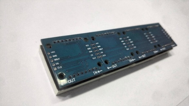
Back view of the MAX7219.
All of the required hardware.
Required Software
The code for this project is by David Bird and can be found in his GitHub repository. You will also need:
Connecting the Hardware
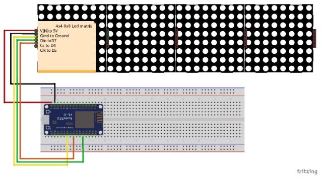
Connect the components listed below, and use the Fritzing diagram as a reference.
LED Matrix | ESP8266 |
|---|
Vcc | 3V (3V on NodeMCU 3V3 on WEMOS) |
GND | GND (G on NodeMCU) |
DIN | D7 (Same Pin for WEMOS) |
CS | D4 (Same Pin for WEMOS) |
CLK | D5 (Same Pin for WEMOS) |
Connections between the LED matrix and ESP8266.
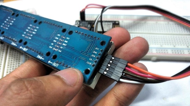
Connections made to the LED matrix.
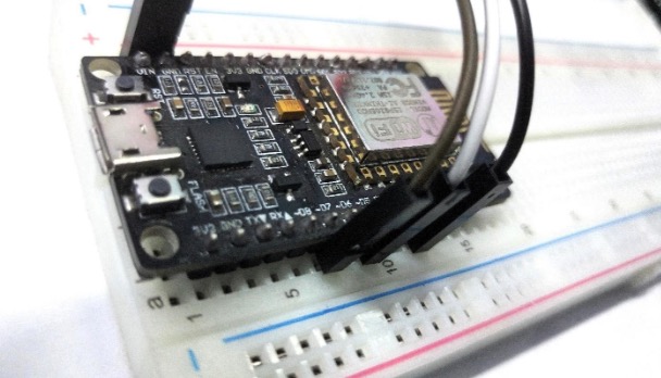
Connections made to the ESP8266.
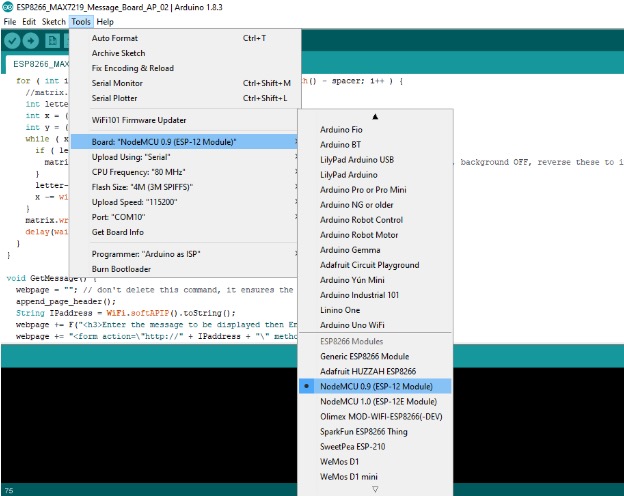
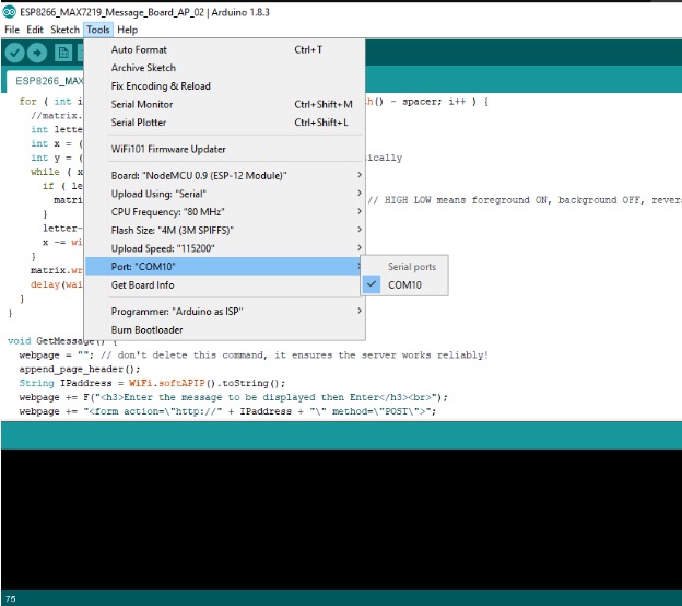
Setting Up Arduino IDE
Open Arduino IDE and install the libraries listed earlier in this tutorial. Next, select the board and upload the source code given below. Make sure to insert your own SSID and password in the marked section of the code.
Once this is set up, upload the source code from GitHub linked under Required Software.
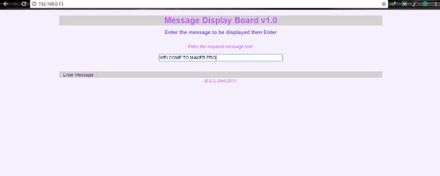
Sending Messages to the LED Matrix
Once the code is in your ESP and the pins are connected, power everything up. This source code creates a web page on your ESP that's accessible through any browser. You just need to find the IP address for it and type it as your URL.
You can find the IP address of the ESP8266 using a terminal Wi-Fi scan command like nmap if you are on Ubuntu:
sudo apt-get install nmap
nmap -sn 192.168.1.0/24
Otherwise, you can also run the following code on the ESP8266 to print its IP address on the serial monitor.
#include <ESP8266WiFi.h>        // Include the Wi-Fi library
const char* ssid     = "SSID";         // The SSID (name) of the Wi-Fi network you want to connect to
const char* password = "PASSWORD";     // The password of the Wi-Fi network

void setup() {
  Serial.begin(115200);         // Start the Serial communication to send messages to the computer
  delay(10);
  Serial.println('\n');

  WiFi.begin(ssid, password);             // Connect to the network
  Serial.print("Connecting to ");
  Serial.print(ssid); Serial.println(" ...");

  int i = 0;
  while (WiFi.status() != WL_CONNECTED) { // Wait for the Wi-Fi to connect
    delay(1000);
    Serial.print(++i); Serial.print(' ');
  }

  Serial.println('\n');
  Serial.println("Connection established!");
  Serial.print("IP address:\t");
  Serial.println(WiFi.localIP());         // Send the IP address of the ESP8266 to the computer
}

void loop() { }
And you're set! You can change the message displayed on the LED matrix as often as you'd like from this screen.