Learn how to build a simple IoT-connected door alarm using an ESP8266 and a Hall effect sensor.
In this article, I’ll discuss what Hall effect sensors are and how you can use one to build a simple device that will sense whether a door is opened or closed and that can be accessed via your home network to check its state.
What is a Hall Effect Sensor?
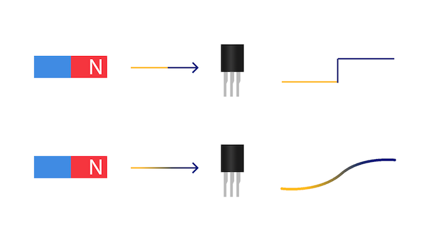
Hall effect sensors can be used to measure the strength of a magnetic field. You can choose between digital and analog sensors. The digital types output a high signal when a certain condition is met while the analog sensing devices output a voltage proportional to the magnitude of the magnetic field:
Digital vs. analog Hall effect sensors.
Some sensors have a built-in latch that retains a state until the magnetic field is reversed. For example: If you have a latched digital type sensor that reacts to the north pole of a magnet and you move a magnet’s north pole close to the sensor, it’ll pull the output high and will remain in that state until you bring the other pole of the magnet close to the sensor.
Refer to your component’s datasheet for details. I used an A3144 Hall effect sensor that outputs a low state whenever the north pole of a magnet is close. The US5881 is a more modern replacement that works in a similar way.
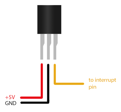
Hall effect sensors have three pins: two supply power (GND and +3.3V or +5V) and the third one is the output line. The two power lines connect to the microcontroller’s power pins and the third one goes to an interrupt pin (D2 in my case):
Hall effect sensors have three pins: two supply power (GND and +3.3V or +5V) and the third is an output line.
Note that some sensors might have a different pin configuration. Consult your device’s datasheet for more details.
Reading the Sensor Values
After connecting the Hall effect sensor according to the image above, it’s time to test it. As mentioned before, the sensor, I used, is a digital type without a latch. This means, that its output pin will go high whenever a magnet’s north pole is close to it and it will be pulled low whenever the magnet is removed.
By connecting the output line to an interrupt pin (D2) of the Arduino compatible NodeMCU, I can react to events when they happen. As a first test, I wrote this short test script that outputs the state of the sensor when it changes:
#define INTERRUPT_PIN D2

void setup()
{
  Serial.begin(9600);

  pinMode(INTERRUPT_PIN, INPUT_PULLUP);
  attachInterrupt(digitalPinToInterrupt(INTERRUPT_PIN), doorChanged, CHANGE);
}

void doorChanged()
{
  if(digitalRead(INTERRUPT_PIN) == 0)
  	Serial.println("The door got closed");
  else
  	Serial.println("The door got opened!");
}

void loop()
{}
As you can see, the code is straightforward and easy to understand. However, don’t forget to configure the GPIO pin, you want to use, to utilize the internal pull-up resistor before assigning the interrupt event.
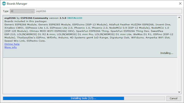
There seems to be a bug in the ESP8266 Arduino package version 2.5.1 and 2.5.2 which will cause an error when you try to execute a sketch that uses interrupts. Consider downgrading to version 2.5.0 if you run into any problems.
Use version 2.5.0 of the ESP8266 Arduino package to avoid a bug that occurs when executing a sketch with interrupts.
The Completed Firmware
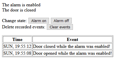
Once the first test was successful, I wrote the firmware for the device. A lot of the code is borrowed from How to Build a Very Simple DIY Home Automation System and I simply updated it for this device. When it boots up, it tries to establish a connection to a wireless network and, once done, it will host a website you can access from your computer to read the sensor value as well as a log of previous events:
Screenshot of the functioning firmware.
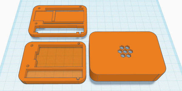
Designing a Case
Case design in Tinkercad.
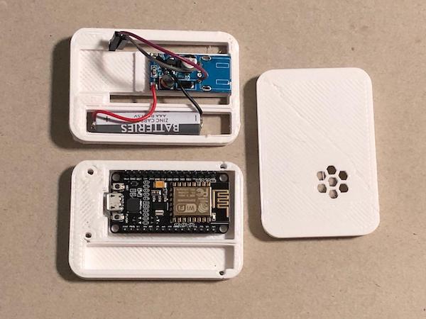
All the components of this project fit into the case. I also added a battery and a small power supply to boost the voltage to five volts. The sensor and the power supply are mounted on the centerpiece.
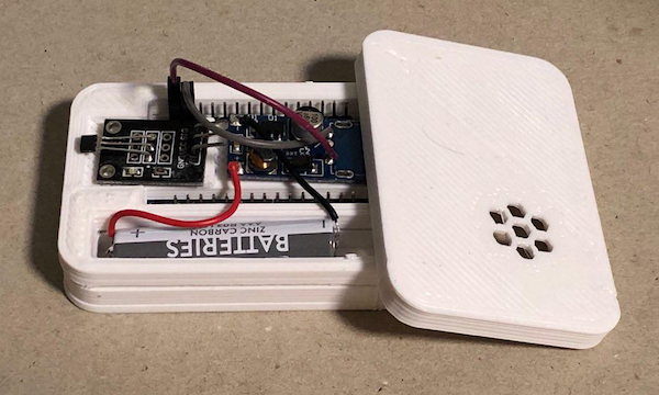
The Arduino and batteries placed in the case.
And the ESP8266 sits underneath it.
The ESP8266 is placed on the other side of the case.
Note: I omitted the wires that connect the microcontroller to the sensor in the images above.
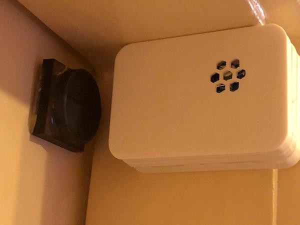
When everything is assembled, mount the device on the doorframe and the magnet on the door itself in a way, that the magnet is recognized, when the door is closed:
The completed door alarm mounted on the doorframe.
As you can see, Hall effect sensors are easy to use and they can be utilized in a wide range of applications. There are a few types of Hall effect sensors that are more or less useful in certain applications. In this case, only a single communication wire is needed that gets connected to the microcontroller’s interrupt pin. The microcontroller hosts a website where the state of the device can be checked.