Using a simple relay board and an ESP8266, this project teaches you how you can automate your home!
Home automation is a hot topic nowadays and even the simplest components of such a system can cost a lot. Therefore building custom devices with cost-effective parts can be an attractive alternative for makers. I’ll discuss the process of building a very basic system in this article.
Before You Begin
Experimenting is fun, but make sure to take all necessary precautions when working with mains voltage which has the potential to kill you. Take a look at the tutorial on controlling high voltage devices to learn how to switch high power devices and this summary of good and cheap IoT developer boards.
The Hardware
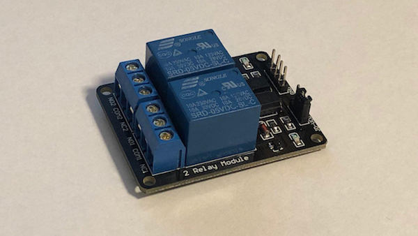
The main component of this build is a simple relay board that can be used to switch voltages up to 250V AC and a maximum current of 10 amperes:
A simple relay board for higher voltage projects.
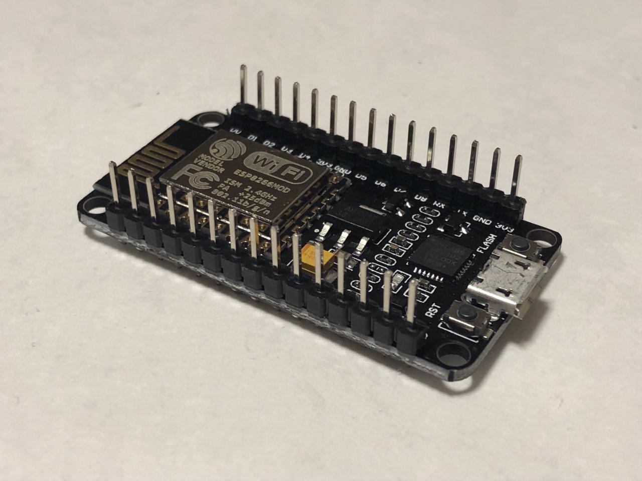
It’ll be controlled by an ESP8266 based IoT developer board which is fully compatible with the Arduino IDE. Alternatively, you could also use a standard Arduino and an ESP8266 (or similar) breakout board.
You only need to make two connections between these devices. One of them is ground, the other is a control line for switching the relay which I chose to connect to D2 (digital pin two) of the developer board.
The relay and the MCU need to be connected to a five-volt power supply which, in my case, is accomplished with a simple DC jack.
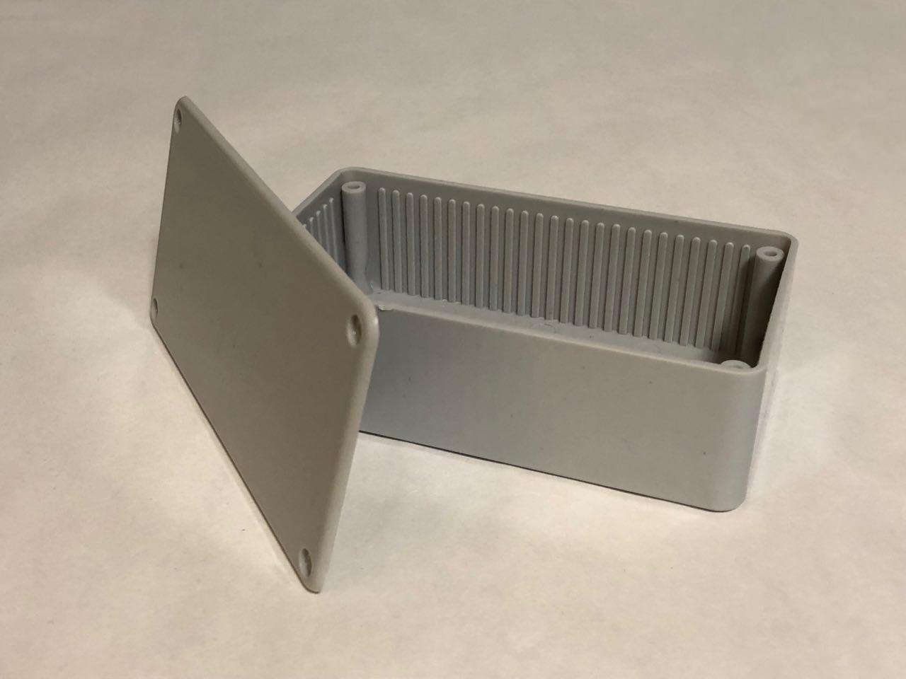
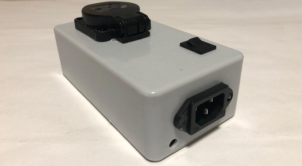
Other than that, you’ll also need a standard mains socket, an IEC plug, preferably one with an earth pin, and a switch for turning the MCU ON and OFF. Furthermore, an enclosure is needed. I chose to go with a standard grey project box:
Use a standard grey project box to house the build.
The Build
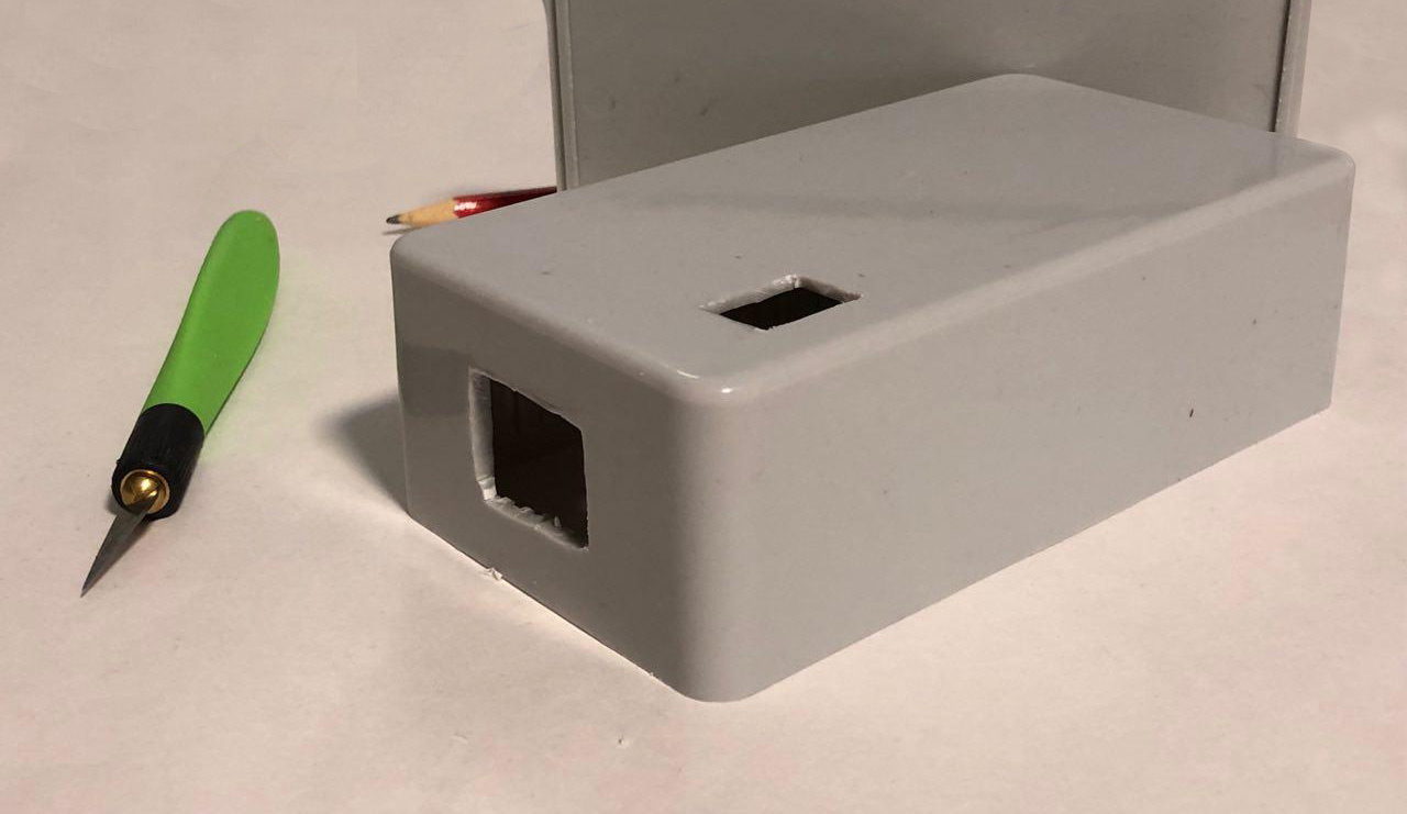
The process of building this device is pretty straight-forward. Start by making the necessary cutouts in the enclosure:
Make the necessary cuts in the project box.
Once you create them, you can mount the components. Most of the components snap in place. I still decided to add hot glue to seal the case so that dust won’t get into it easily:
Use glue to ensure nothing moves and to make the box less susceptible to dust.
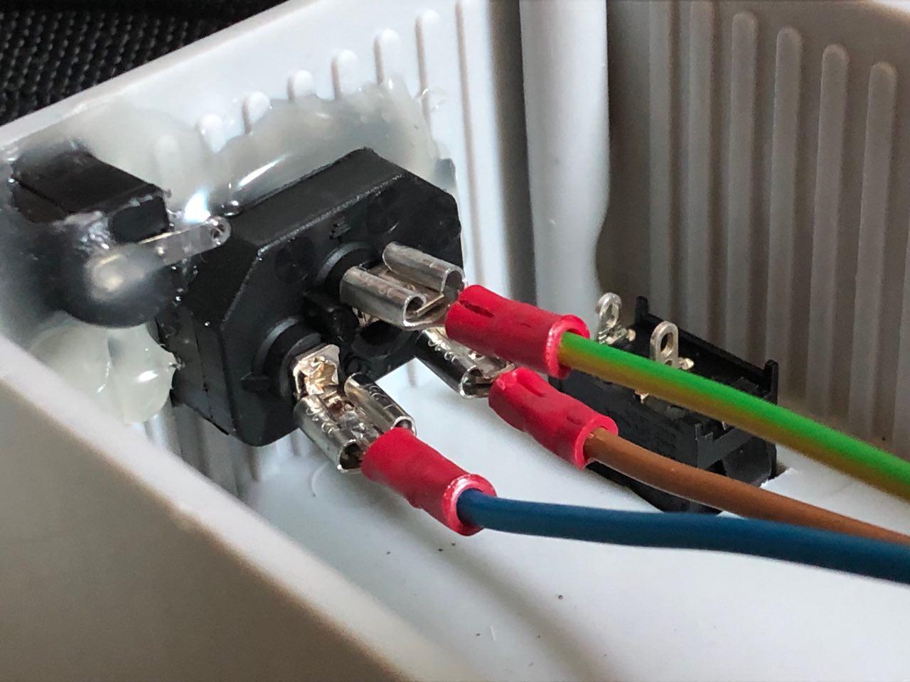
Once that’s done, it’s time to connect these components and the other electronics. I added cable shoes on one side of the three mains wires and connected them to the IEC connector:
Add cable shoes on one side of the three mains wires and connect to the IEC connector.
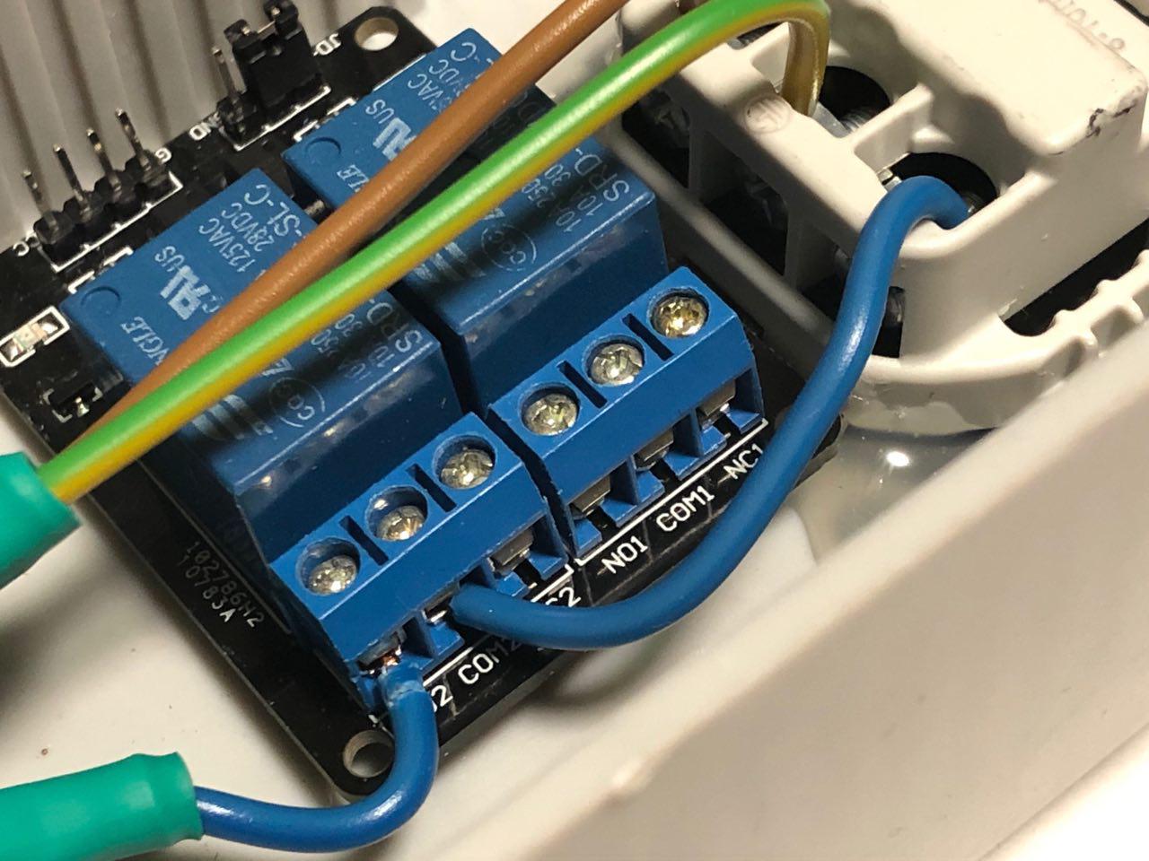
The phase and neutral lines (brown and blue in Europe, black/red and white in the US) may be swapped. The earth connection, however, has to be in the middle. I connected the phase to the mains socket directly and ran the neutral line to the COM2 terminal of the relay before connecting the NO2 (normally open) terminal of the relay to the socket as well:
Connect the phase to the mains socket and run the neutral line to the COM2 terminal of the relay before connecting the NO2 (normally open) terminal of the relay to the socket.
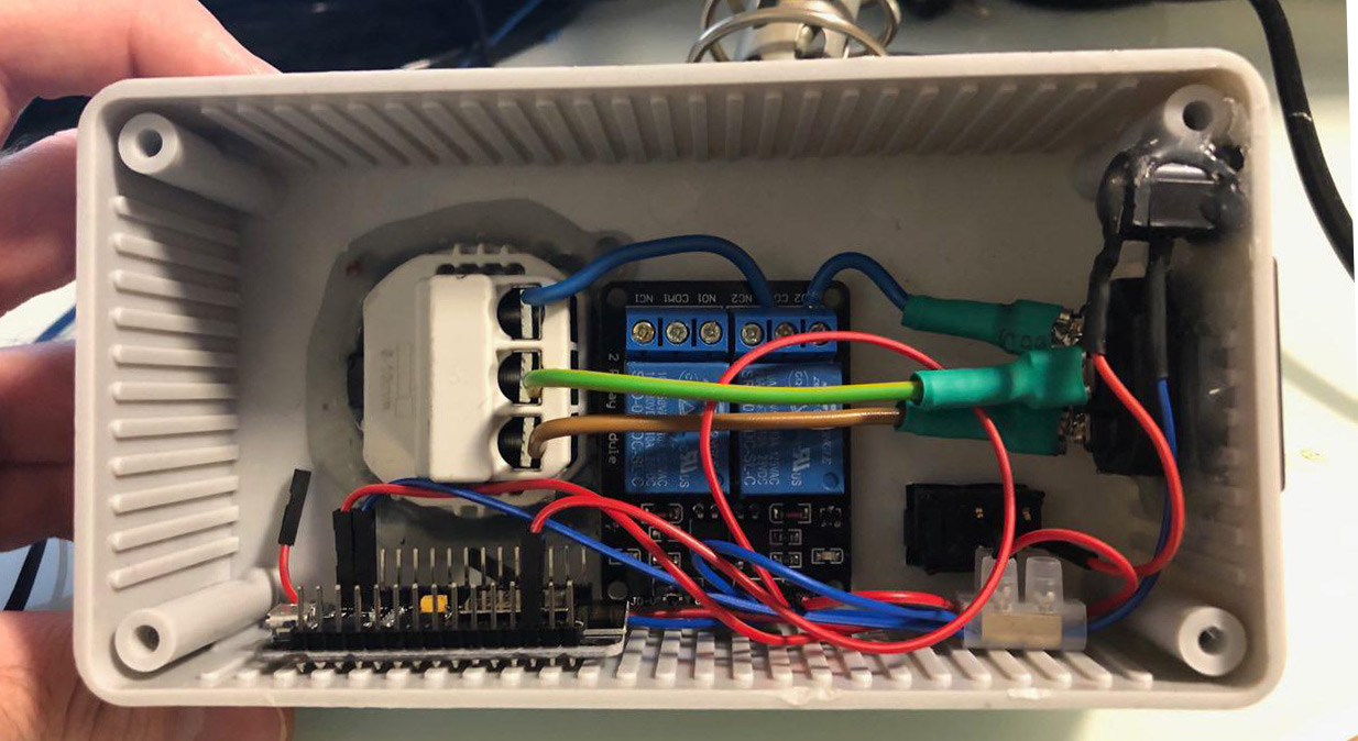
I then added the necessary cables to the DC plug. These are used for supplying the voltage to the microcontroller as well as the relay. The last thing to do is connecting the relay and the MCU, as described above. I then added heat shrink tubing to the critical sections to prevent shorts and test-fitted the components:
Add the necessary cables to the DC plug.
Once everything fits, tuck away the cables and close the case.
The Software
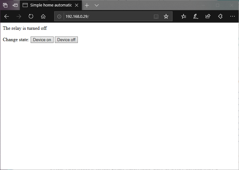
The software that runs on the MCU connects you to your wireless network and accepts client requests on port 80 like a web server. You can then access the device via any web browser:
Access the device via any web browser.
I won’t discuss the code in detail to keep the article short. However, I thoroughly documented the source code so it should be easy to understand. It is available at the end of the article.
Conclusion
As you can see, it’s not terribly difficult to build such a device. Most of the work is done by the software. While this is the most basic approach, you can add sensors, timers, and other devices for automatically controlling the connected appliance. Furthermore, I recommend adding a fuse if you plan on using this device unattended.
Full Project Code
#include <ESP8266WiFi.h>
#define RELAY_PIN D2
const char* ssid = "YOUR_WIFI_NETWORK";
const char* pass = "YOUR_NETWORKS_PASSWORD";
WiFiServer server(80);
void setup()
{
Serial.begin(9600);
// You could add an EEPROM to store the last state if the device gets powered off.
// See: https://maker.pro/arduino/tutorial/how-to-permanently-store-data-on-your-arduino
//
// It's also possible to store the website and stylesheets/additional scripts on an SD
// card and display the files to a client when they connect.
// See: https://maker.pro/arduino/tutorial/how-to-use-an-sd-card-with-your-arduino
//
// However, this simple example will always start with the relay turned on and a very
// basic HTML page with two buttons.
pinMode(RELAY_PIN, OUTPUT);
digitalWrite(RELAY_PIN, HIGH);
// Connect to your local network
WiFi.begin(ssid, pass);
while (WiFi.status() != WL_CONNECTED)
delay(250);
Serial.print("Connected to network: ");
Serial.println(ssid);
// Start the server
// A client will connect to this server to change the state of the relay
server.begin();
Serial.print("Server started with address: ");
Serial.print("http://");
Serial.print(WiFi.localIP());
Serial.println("/");
}
void loop()
{
// Check for incoming connections
WiFiClient client = server.available();
if (!client)
return;
// Wait for the client to send data
while(!client.available())
delay(5);
// Read the first line of the HTTP request
// which will contain something like
// METHOD /requested_url HTTP_VERSION
// for example:
// PUT /dev2?relay=1&state=on HTTP/1.1
// However, for the sake of simplicity this device will
// respond to GET requests so that they can be sent with
// any web browser. Requests to this device will look
// similar to this:
// GET /state=on HTTP/1.1
String request = client.readStringUntil('\r');
client.flush();
int state = 0, error = 0;
// Check, whether the request contains "/state="
if (request.indexOf("state=") != -1)
{
// HIGH and LOW are swapped in this program because my
// relay is turned on when its input pin is pulled LOW.
if(request.indexOf("state=on") != -1)
{
digitalWrite(RELAY_PIN, HIGH);
state = LOW;
}
else if (request.indexOf("state=off") != -1)
{
digitalWrite(RELAY_PIN, LOW);
state = HIGH;
}
else
{
error = 1;
Serial.print("Unknown request: ");
Serial.println(request);
}
}
// Return the response
// If no error occurred, send an HTML page with two buttons
// so that the device can be managed.
// Otherwise, send an error message
if(error == 0)
{
// Return a response header
client.println("HTTP/1.1 200 OK");
client.println("Content-Type: text/html");
// The HTTP response body is separated from the header by an empty line
// (actually a line containing \r\n, but this will work)
client.println("");
// Return the response body (an html page)
client.println("<html>");
client.println("<head>");
client.println("<title>Simple home automation</title>");
client.println("</head>");
client.println("<body>");
client.print("The relay is turned ");
client.print(state==HIGH?"on":"off");
client.println("<br> <br>");
client.println("Change state:");
client.println("<a href=\"/state=on\"><button>Device on</button></a>");
client.println("<a href=\"/state=off\"><button>Device off</button></a>");
client.println("</body>");
client.println("</html>");
}
else
{
// Return a response header
client.println("HTTP/1.1 400 Bad Request");
client.println("Content-Type: text/html");
client.println("");
client.println("<html>");
client.println("Unknown request parameter supplied!<br/>");
client.println("<a href=\"/\">Back to main page</a>");
client.println("</html>");
}
}