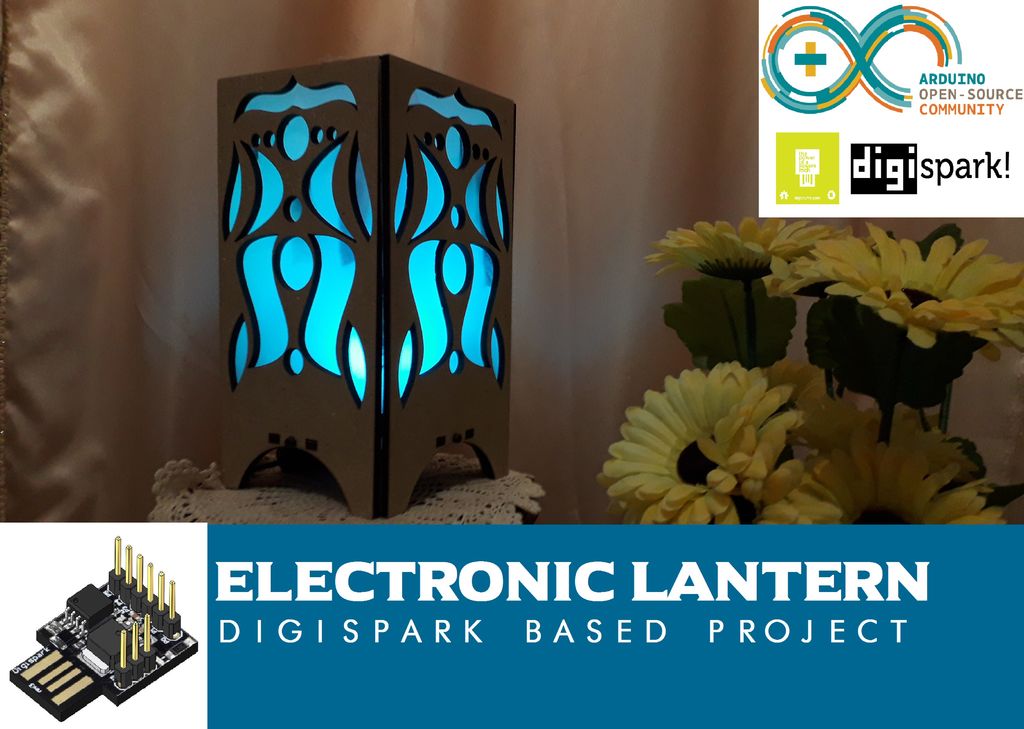
this time it will be so easy for all of you guys to make this project which is an electronic lantern.
Introduction: Digispark Lantern (ATtiny85 Project)
Selecting the right components depending on your project functionalities.Making the circuit to connect all the choosen components.Assemble all the project parts.Interface the Digispark ATtiny85 Dev board to control the lantern.
Hey what’s up guys, yet again a new instructable as usual I will show you how to make a super cool project based on electronics, and this time it will be so easy for all of you guys to make this project which is an electronic lantern, since we’ve been making robots and a bit complicated projects, I decided to make a basic one this time to allow any one of you to make it and for sure there are some basic electronic knowledge required out there but do not think twice to try it because it is an amazing one.
This project is so handy to make specially after getting the customized PCB that we’ve ordered from JLCPCB to improve the appearance of our Lanter and also there is enough documents and codes in this guide to allow you create your own lantern.
We've made this project in just 2 days only, just one day to finish the hardware making and the assemble, then a second day to prepare the code and perform the tests.
Before starting let’s see first
What you will learn from this instructable :
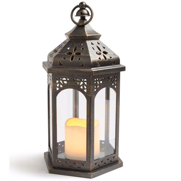
Step 1: What Is a Lantern!
We all know Lanternsand what people are using them for, Lanterns were usually made from a metal frame with several sides (usually four, but up to eight), commonly with a hook or hoop of metal on top. Windows of some translucent material would be fitted in the sides, now usually glass or plastic but formerly thin sheets of animal horn, or tinplate punched with holes or decorative patterns; though some antique lanterns have only a metal grid, clearly indicating their function was that outlined below.
So it is a piece of a holding box that hold a candle to light up an area with its flame, in our case we will design a box to hold the light source which is an electronic printed circuit that contains some bright LEDs and for the flame trembling we will use a 12V DC fan to tremble some pieces of cloth that we will stick in the inner side of the box and also the light will change color because of the RGB LEDs that we are using and the whole system will be controlled by a digispark Attiny85 board.
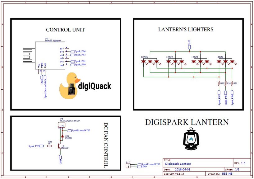
Step 2: Digispark ATtiny85 Is the Heart of Our Project
we are using this board because of its tiny size that suites perfectly our project and also because of the IO pins that it has since we need three PWM pins to control the Light color and one digital output to control the DC fan through a transistor and all the required IO pins are available in this small board.
Talking about Digispark ATtiny85 board produced by Digistump which is a family owned and operated business in the Portland producing development boards based on Atmel microcontrollers which makes them products Arduino compatible so you can easily flash these boards using Arduino IDE and you can get much more details on how to use this kind of boards through this Tutorial where we've expalained in details how to interface Digispark ATtiny85 with Arduino IDE.
The board has an ATtiny (also known as TinyAVR) which is a family of microcontrollers developed by Atmel beginning in the late 1990s (later Microchip Technology acquired Atmel in 2016). These chips have a modified Harvard architecture 8-bit RISC processor core. The smallest in their AVR family of microcontrollers are the ATtiny series (8-bit core and fewer features, fewer I/O pins, and less memory than other AVR series).
Why Digispark ATtiny85!
we are using this board because of its tiny size that suites perfectly our project and also because of the IO pins that it has since we need three PWM pins to control the Light color and one digital output to control the DC fan through a transistor and all the required IO pins are available in this small board.
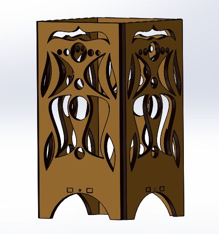
Step 3: The Lantern Design
The box design is so simple and a basic one so you can just follow the same design idea to create your own design with the shape that suites you more.
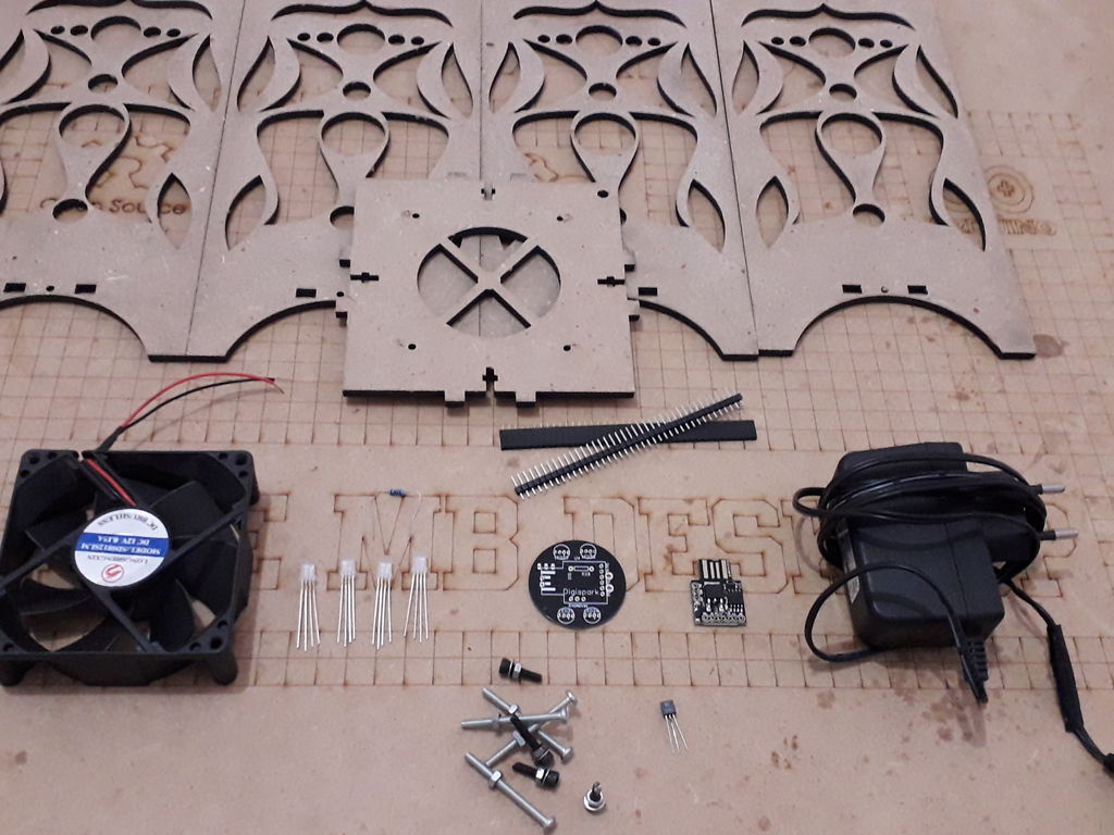
As usual we start with the hardware part and talking hardware we will start with the lantern box, so I designed this shape using solidworks software which allows me to generate a DXF files to upload them in a CNC laser cutting machine in order to produce the designed box; we used a 5mm MDF wood material to create this box, perfect, cheap and it add a better appearance for our project.
you can download the DXF files that we've used to produce this lantern box through this download link.
The box design is so simple and a basic one so you can just follow the same design idea to create your own design with the shape that suites you more.
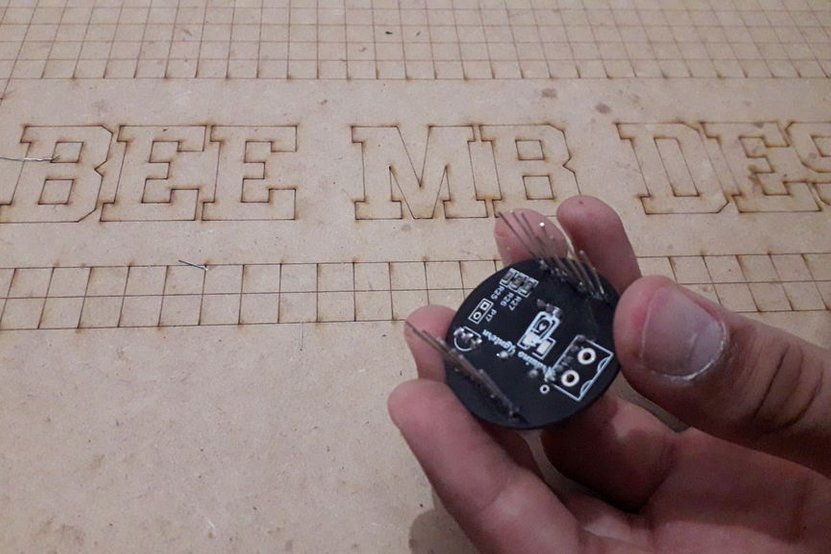
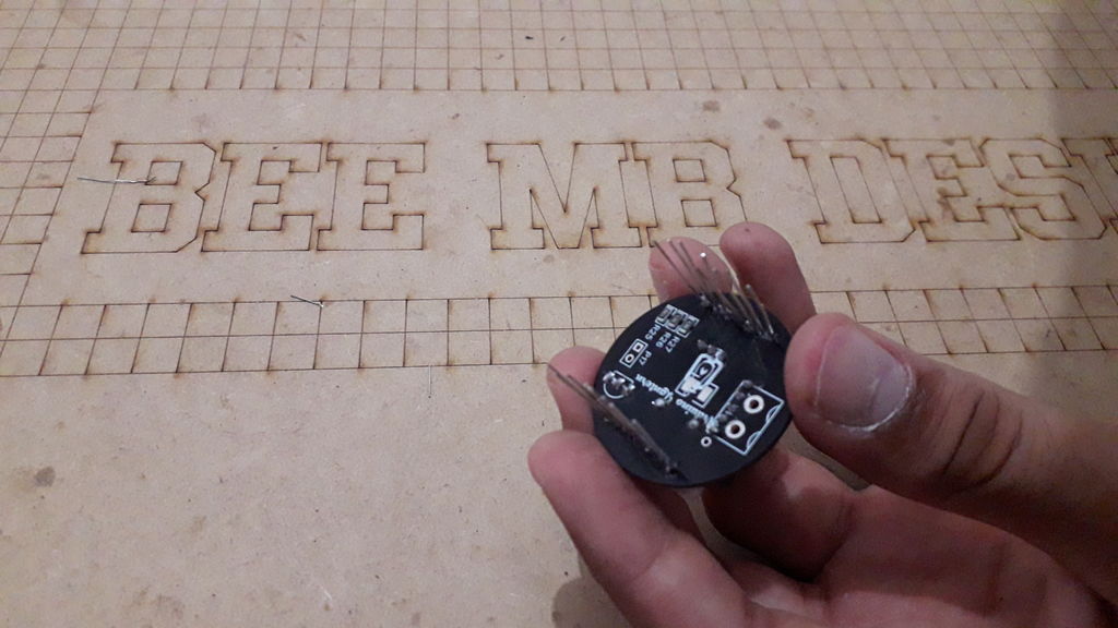
Step 4: The PCB Making (Produced by JLCPCB)
you can get the Gerber files for the circuit through this download link
About JLCPCB (Shenzhen JIALICHUANG Electronic Technology Development Co., Ltd.), is the largest PCB prototype enterprise in China and a high-tech manufacturer specializing in quick PCB prototype and small-batch PCB production. With over 10 years of experience in PCB manufacturing, JLCPCB has more than 200,000 customers at home and abroad, with over 8,000 online orders of PCB prototyping and small quantity PCB production per day. The annual production capacity is 200,000 sq.m. for various of 1-layer, 2-layer or multi-layer PCBs. JLC is a professional PCB manufacturer featured of large scale, well equipment, strict management and superior quality.
Back to our project
In order to produce the PCB, I have compared the price from many PCB producers and I chose JLCPCB the best PCB suppliers and the cheapest PCB providers to order this circuit. All what I need to do is some simple clicks to upload the gerber file and set some parameters like the PCB thickness color and quantity, then I’ve paid just 2 Dollars to get my PCB after five days only.
As it shows the picture of the related schemtic, I have used a Digispark ATtiny85 dev board to control the whole system. you can get the schematic PDF file through this download link.
Best quality
the quality making of these PCBs increase our confidence to use JLCPCB service in all our projects, as you see guys the PCB is relatively small enough to fit the placement inside the Lantern box and also the labels and logos are very well produced too.
you can get the Gerber files for the circuit through this download link
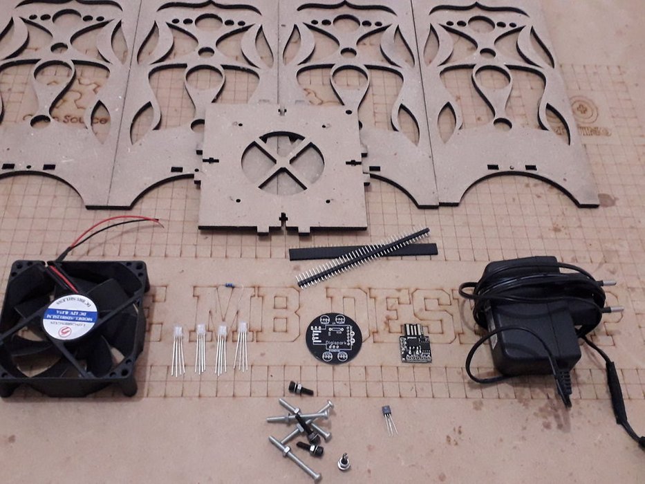
Step 5: Full Review of the Ingredients
The PCB that we order from JLCPCBDigispark ATtiny85 dev board https://amzn.to/2CSHIgG4 RGB LEDs 5mm https://amzn.to/2NyEnaS12V DC fan https://amzn.to/2Qnn0btBC170 transistor https://amzn.to/2NyiIjg1K Ohm resistor https://amzn.to/2N38xUa12V DC power adaptor https://amzn.to/2NCH1wqSome header connectors https://amzn.to/2x52BiB
We have everything ready so we need to review the necessary components that we need for this projet:
Step 6: Soldering and Assembly
After that, move to the electronic assembly and we solder all the components to the PCB. you will find on the top silk layer a label of each component indicating its placement on the board and this way you will be 100% sure that you will not make any soldering mistakes.
Now we move directly to the assembly of the box, it is so simple since we created the screw placement in the design but first we need to cover each part with this tracing paper then we stick the pieces of cloth on the box sides.
After that, move to the electronic assembly and we solder all the components to the PCB. you will find on the top silk layer a label of each component indicating its placement on the board and this way you will be 100% sure that you will not make any soldering mistakes.
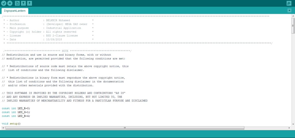
Step 7: Digispark Code and Test Validation
Now I prepared this code that switchs the LEDs color and turns on the fan, we upload the code and place the board in its placement and as you see, here are our LEDs switching them colors.
You can get the source code for free through this download link.
As you can see guys in the pictures above, the Lantern is switching its light color following all the instructions that we've created through thr source code and still some other improvements to perform in order to make it much more butter.
I expect that you write down in the comments section all your ideas to improve this project and also to show us pictures if you try a similar one.
Thnak you