This project presents the code of an Arduino-based programming solution for the SLG46824/6.
In this project, we show how to use the SLG46824/SLG46826 Arduino programming sketch to program an SLG46824/SLG46826 GreenPAK Multiple-Time Programmable (MTP) device.
Most GreenPAK devices are One-Time Programmable (OTP), meaning that once their Non-Volatile Memory bank (NVM) is written, it cannot be overwritten. GreenPAKs with the MTP feature, like the SLG46824 and SLG46826, have a different type of NVM memory bank that can be programmed more than once.
We’ve written an Arduino sketch that allows the user to program an MTP GreenPAK with a few simple serial monitor commands. In this project, we use an SLG46826 as our GreenPAK with MTP.
We provide sample code for the Arduino Uno using an open-source platform based on C/C++. Designers should extrapolate the techniques used in the Arduino code for their specific platform.
For specific information regarding I2C signal specifications, I2C addressing, and memory spaces, please reference the GreenPAK In-System Programming Guide provided on the SLG46826 product page. This project provides a simple implementation of this programming guide.
The complete design file can be found here. It was created in the GreenPAK Designer software (a part of the Go Configure™ Software Hub).
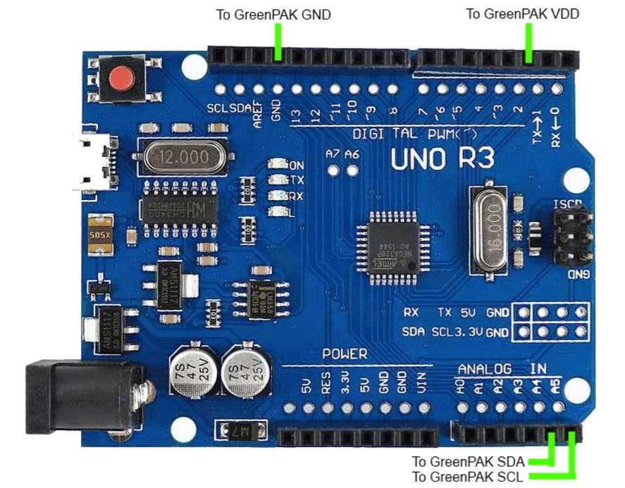
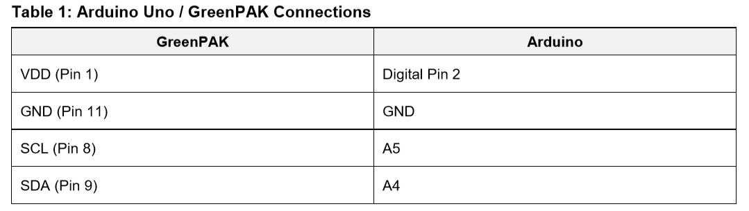
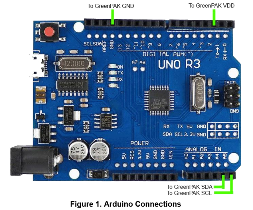
1. Arduino-GreenPAK Connections
To program the NVM of our SLG46826 GreenPAK with our Arduino sketch, we'll first need to connect four Arduino Uno pins to our GreenPAK. You can connect these pins directly to the GreenPAK Socket Adapter or to a breakout board with the GreenPAK soldered down.
Please note that external I2C pull up resistors are not shown in Figure 1. Please connect a 4.7 kΩ pull up resistor from both SCL and SDA to the Arduino’s 3.3 V output.
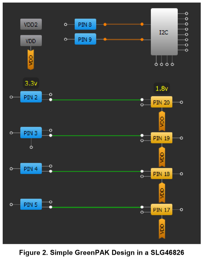
2. Exporting GreenPAK NVM Data from a GreenPAK Design File
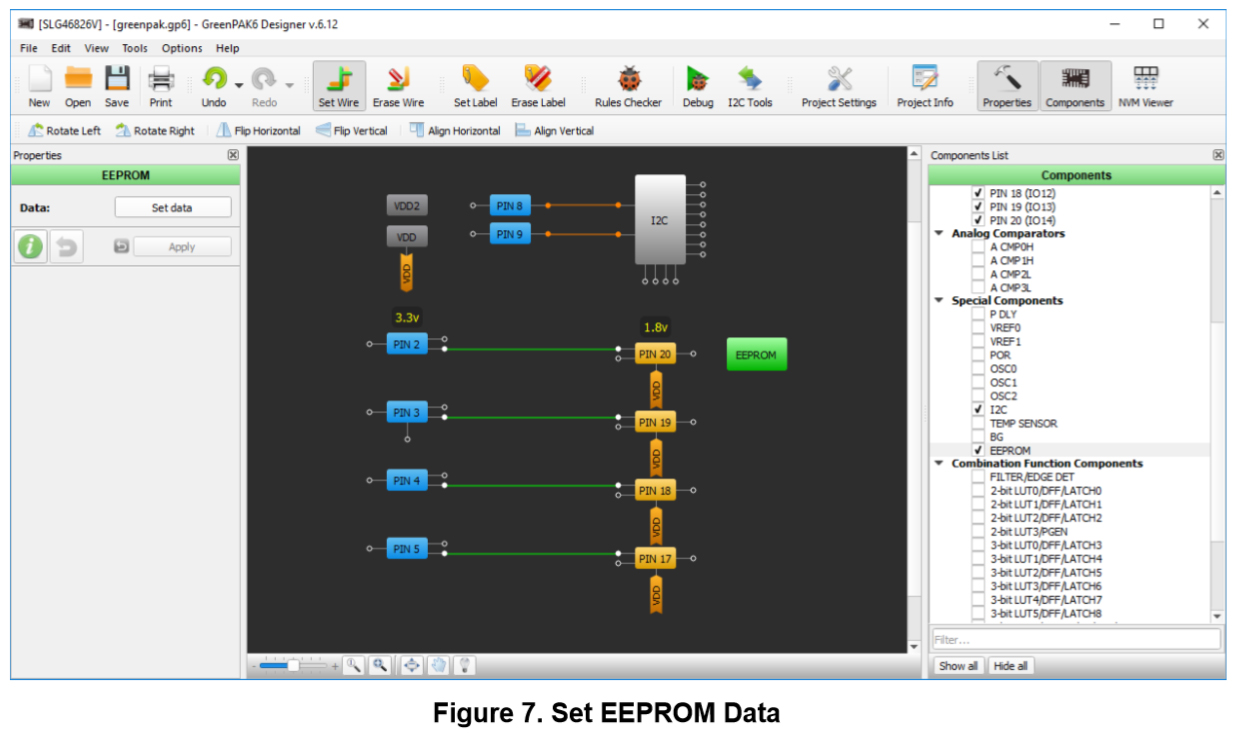
We'll put together a very simple GreenPAK design to illustrate how to export the NVM data. The design below is a simple level shifter where the blue pins on the left are tied to VDD (3.3 V), while the yellow pins on the right are tied to VDD2 (1.8 V).
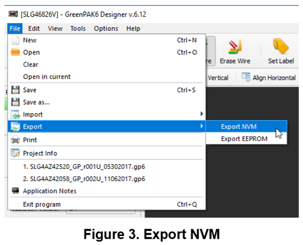
To export the information from this design, you need to select File → Export → Export NVM, as shown in Figure 3.
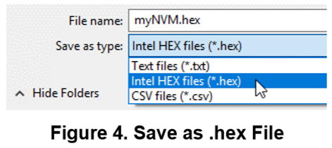
You will then need to select Intel HEX Files (*.hex) as the file type and save the file.
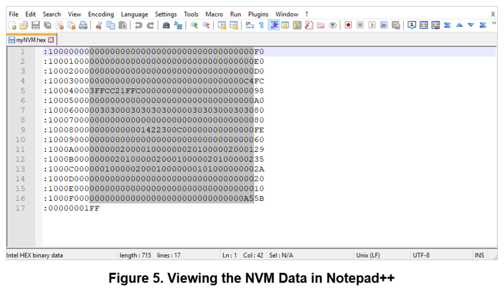
Now, you'll need to open the .hex file with a text editor (like Notepad++). To learn more about the Intel’s HEX file format and syntax, check out its Wikipedia page. For this application we’re only interested in the data portion of the file as shown in Figure 5.
Highlight and copy the 256 bytes of NVM configuration data located within the HEX file. Each line that we are copying is 32 characters long, which corresponds to 16 bytes.
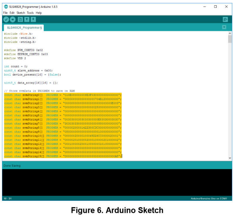
Paste the information into the highlighted nvmString[] section of the Arduino sketch as shown in Figure 6. If you’re using a non-Arduino Microcontroller, you could write a function to parse the nvmData saved in the GreenPAK .GP6 file. (If you open a GreenPAK file with a text editor, you’ll see that we store project information in an easily-accessible XML format.)
To set the EEPROM data for your GreenPAK design, select the EEPROM block from the components panel, open its properties panel, and click "Set Data."
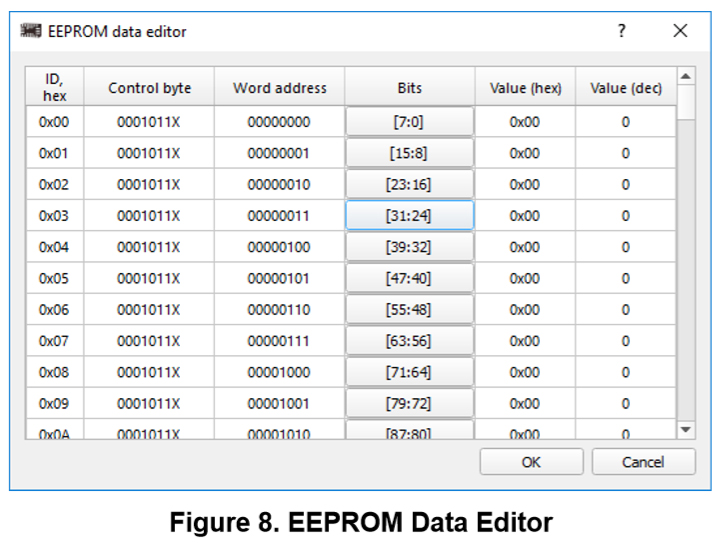
Now you can edit each byte in the EEPROM individually with our GUI interface.
Once your EEPROM data is set, you can export it to a HEX file using the same method described previously for exporting the NVM data. Insert these 256 bytes of EEPROM data into the eepromString[] section of the Arduino sketch.
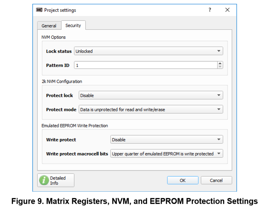
For each custom design, it is important to check the protection settings within the “Security” tab of the project settings. This tab configures the protection bits for the matrix configuration registers, the NVM, and the EEPROM. Under certain configurations, uploading the NVM sequence can lock the SLG46824/6 to its current configuration and remove the MTP functionality of the chip.
3. Use the Arduino Sketch
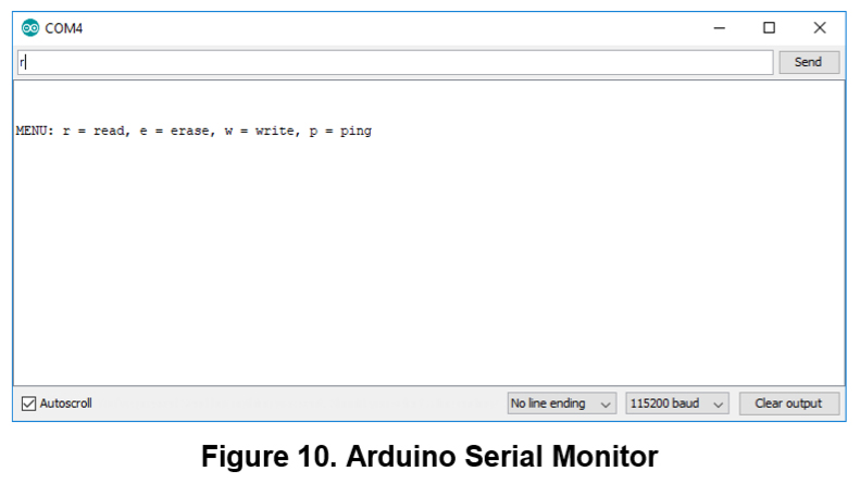
Upload the sketch to your Arduino and open the serial monitor with a 115200 baud rate. Now you can use the sketch's MENU prompts to perform several commands:
- Read - reads either the device’s NVM data or EEPROM data using the specified slave address
- Erase - erases either the device’s NVM data or EEPROM data using the specified slave address
- Write - Erases and then writes either the device’s NVM data or EEPROM data using the specified slave address. This command writes the data that is saved in the nvmString[] or eepromString[] arrays.
- Ping - returns a list of device slave addresses that are connected to the I2C bus
The results of these commands will be printed to the serial monitor console.
4. Programming Tips and Best Practices
Over the course of supporting the SLG46824/6, we’ve documented a few programming tips to help avoid common pitfalls associated with erasing and writing to the NVM address space. The following subsections outline this topic in more detail.
4.1. Executing Precise 16-Byte NVM Page Writes:
When writing data to the SLG46824/6’s NVM, there are three techniques to avoid:
- Page writes with less than 16 bytes
- Page writes with more than 16 bytes
- Page writes that don’t begin at the first register within a page (IE: 0x10, 0x20, etc.)
If any of the above techniques are used, the MTP interface will disregard the I2C write to avoid loading the NVM with incorrect information. We recommend performing an I2C read of the NVM address space after writing to verify correct data transfer.
4.2. Transferring NVM Data into the Matrix Configuration Registers
When the NVM is written, the matrix configuration registers are not automatically reloaded with the newly written NVM data. The transfer must be initiated manually by cycling the PAK VDD or by generating a soft reset using I2C. By setting register <1601> in address 0xC8, the device re-enables the Power-On Reset (POR) sequence and reloads the register data from the NVM into the registers.
4.3. Resetting the I2C Address after an NVM Erase:
When the NVM is erased, the NVM address containing the I2C slave address will be set to 0000. After the erase, the chip will maintain its current slave address within the configuration registers until the device is reset as described above. Once the chip has been reset, the I2C slave address must be set in address 0xCA within the configuration registers each time the GreenPAK is power-cycled or reset. This must be done until the new I2C slave address page has been written in the NVM.
5. Errata Discussion
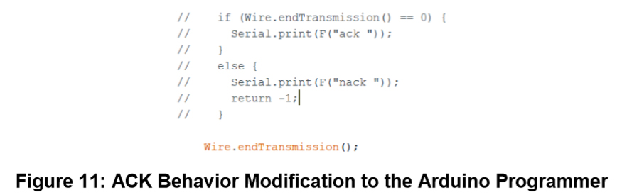
When writing to the “Page Erase Byte” (Address: 0xE3), the SLG46824/6 produces a non-I2C compliant ACK after the “Data” portion of the I2C command. This behavior might be interpreted as a NACK depending on the implementation of the I2C master.
To accommodate for this behavior, we modified the Arduino programmer by commenting out the code shown in Figure 11. This section of code checks for an I2C ACK at the end of every I2C command in the eraseChip() function. This function is used to erase the NVM and EEPROM pages. Since this section of code is located in a For loop, the “return -1;” line causes the MCU to pre-maturely exit the function.
Despite the presence of a NACK, the NVM and EEPROM erase functions will execute properly. For a detailed explanation of this behavior, please reference “Issue 2: Non-I2C Compliant ACK Behavior for the NVM and EEPROM Page Erase Byte” in the SLG46824/6 errata document (Revision XC) on Dialog’s website.
Conclusion
In this project, we describe the process of using the provided Arduino programmer to upload custom NVM and EEPROM strings to a GreenPAK IC. The code in the Arduino Sketch is thoroughly commented, but if you have any questions regarding the sketch, please contact one of our Field Application Engineers or post your question on our forum. For more in-depth information regarding MTP programming registers and procedures, please reference In-System Programming Guide.