Learn how you can program your ATtiny MCU using ISP headers with a USB ASP programmer.
If you've decided that an ATtiny MCU is the best route for your project, it's time to pick a programming method.
The first ATtiny programming method I covered introduced using an IC test clip as a means of interfacing the MCU with Arduino IDE. Next, we'll cover the method of using an ISP header on the PCB and an AVR programmer to interface with a computer.
Integrating an ISP header into the PCB design is the most common method for programming AVR microcontrollers on an assembled PCB. This programming method is extremely common for small- to medium-size production runs as it allows the microcontroller programming process to be done as part of the process of assembling the PCB.
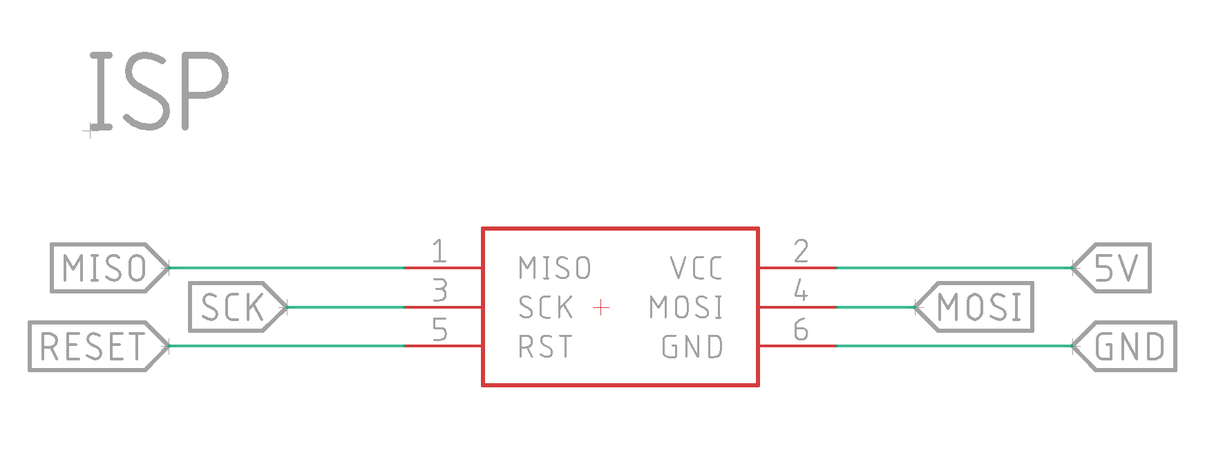
What is an ISP Header?
An in-system programming (ISP) header is typically a six-pin, 2x3 header, although some designs use eight-pin, 2x4 header. There are even some designs that use a ten-pin, 2x5 header.
An ISP header provides a standardized interface for carrying programming signals from an external programmer to a chip.
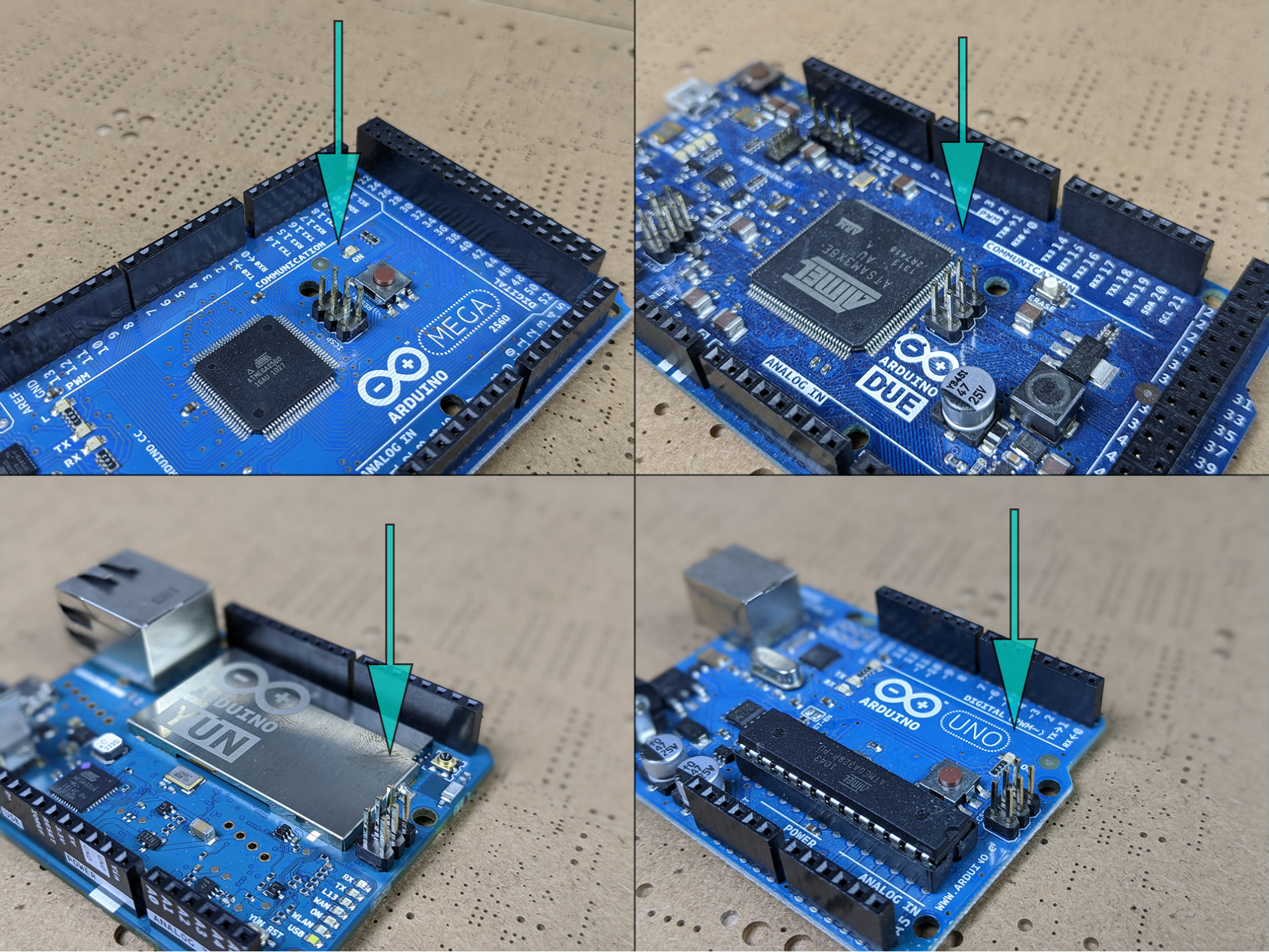
You will find ISP headers on quite a few DIY microcontroller boards, including many versions of Arduino products.
ISP headers can also be found on popular DIY boards, like the Arduino Uno.
In-system programming is common in electronics manufacturing because it allows boards to be programmed as part of the production process, rather than requiring a separate programming step.
For example, it is possible to purchase pre-programmed microcontrollers from various vendors that only need to be soldered to a PCB to complete production. However, this adds complexity, cost, and logistical overhead, meaning it is more common with very large production runs.
For smaller-scale manufacturing, the use of ISP headers in designs allows boards to be programmed in a single production stage.
Ways to Program an ATtiny via an ISP Header
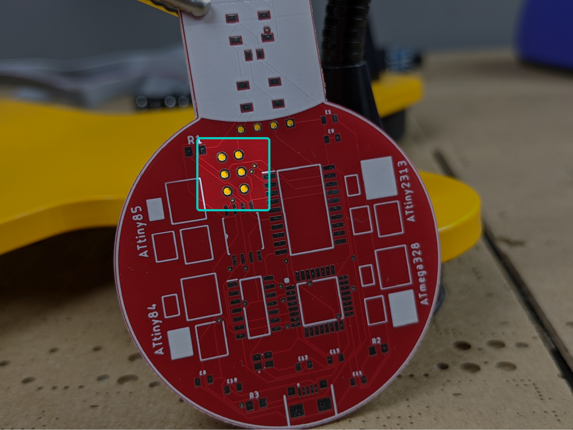
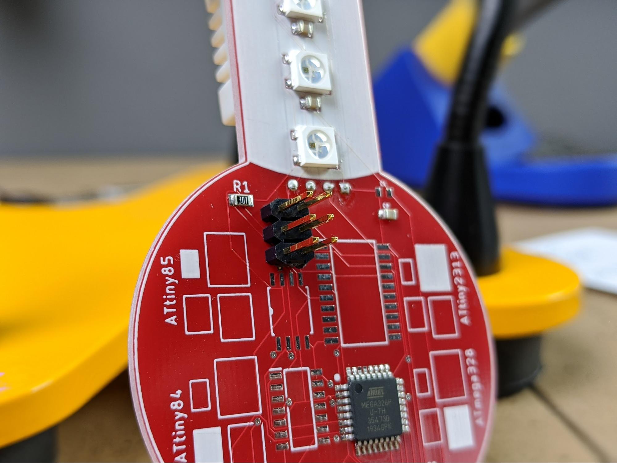
The testing PCB used in this tutorial has an ISP header to program any of the different ATtiny microcontrollers that can be placed on the board.
The ISP header on the test PCB is this set of six pins.
There are two common methods for interfacing with ISP programming headers:
- Using pogo pins
- By soldering a 2x3 pin male header to the board
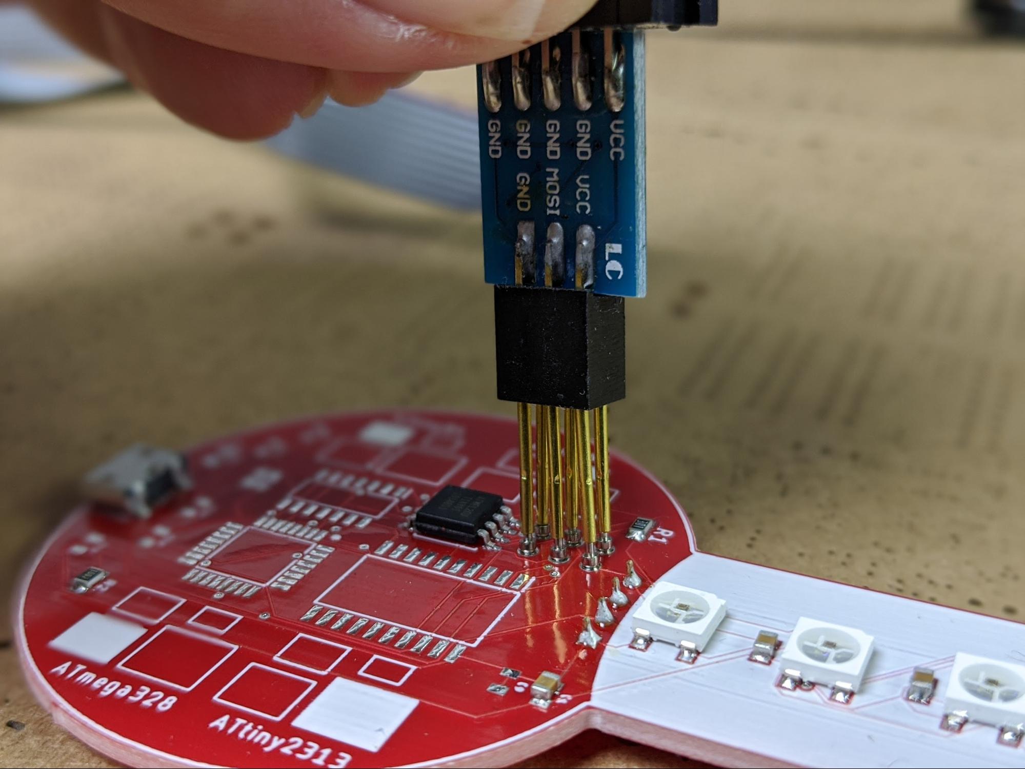
Interfacing With Pogo Pins
The first is by forming a temporary electrical connection using pogo pins. Pogo pins are spring-loaded contact pins that allow reliable but temporary electrical connections.
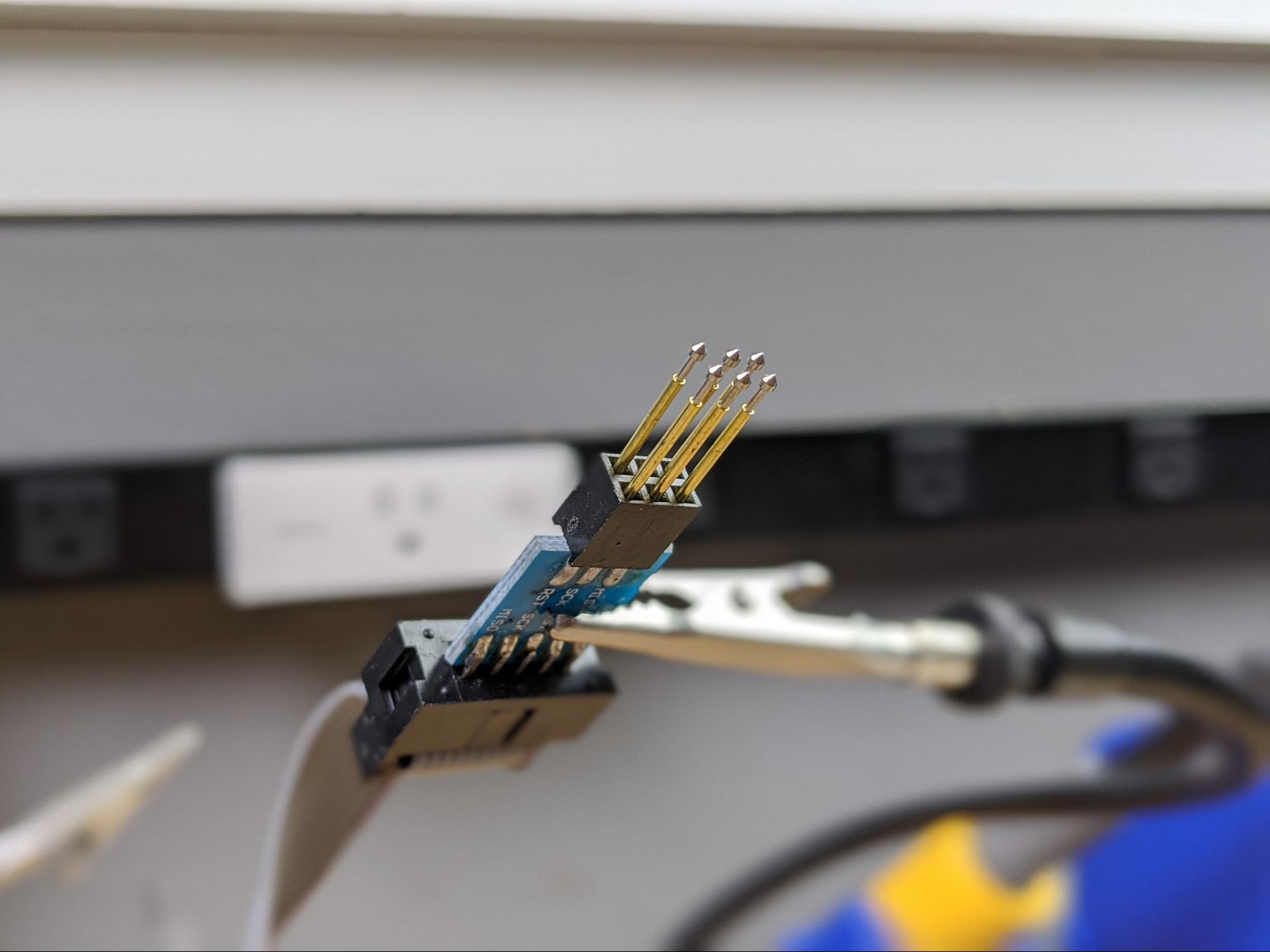
It is more common for manufacturers to use jigs to make connecting to ISP headers and completing the programming process easier. However, a simple system for programming prototype boards using pogo pins can be created by simply inserting pogo pins into the AVR programmer.
A rudimentary pogo pin ISP programmer can be created by inserting pogo pins into the AVR programming tool.
The AVR programmer can be connected to the ISP header using pogo pins.
Interfacing With a 6-pin Male Header
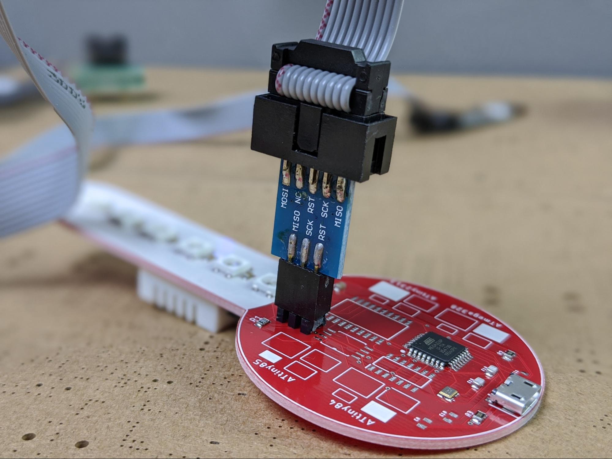
The second method for connecting to ISP headers is by soldering a 2x3 pin male header to the board.
Header pins can be used to enable easy connections to the ISP header.
This arrangement allows the AVR programming tool to be simply plugged into the board. Using a 2x3 pin header allows for a more secure connection, although it also adds size and cost to the PCB.
The AVR programmer can be directly plugged into the ISP header pins.
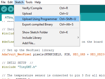
There is also a small difference in the way the Arduino IDE uploads a sketch to the microcontroller via an AVR programmer versus a USB connection or IC test clip.
Rather than pressing the Upload button, select Sketch > Upload Using Programmer.
To upload code, select Upload Using Programmer from the Sketch menu.
When Integrating ISP Headers is the Best Choice
Integrating ISP programming headers into a PCB design provides a standardized interface for programming microcontrollers after they have been soldered onto a PCB.
This method is useful both for prototyping and for manufacturing. ISP headers, or sometimes custom-designed headers, are the most commonly-used methods for programming microcontrollers in products during assembly. The ISP header allows an AVR programmer to be easily connected to the microcontroller.