In this part of our series on PCB art, we program the ATmega328 MCU embedded on the PCB using the ISP header.
The final step in creating the Maker Pro robot PCB badge is programming the onboard ATmega328p microcontroller to run the board.
We've done a lot with our custom-made PCB badge to get to this point! If you haven't read the other steps necessary for creating PCB art, take a moment to check them out:
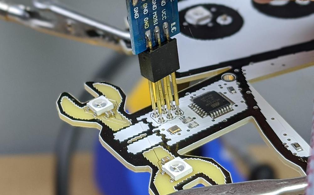
Now, onto programming the ATmega328. There are several ways to program embedded microcontrollers; for this tutorial, we will use an in-circuit programming (ISP) header included on the robot’s right arm near the microcontroller.
We can program the ATmega328 using this ISP header located near the microcontroller.
How to Prepare the Programmer
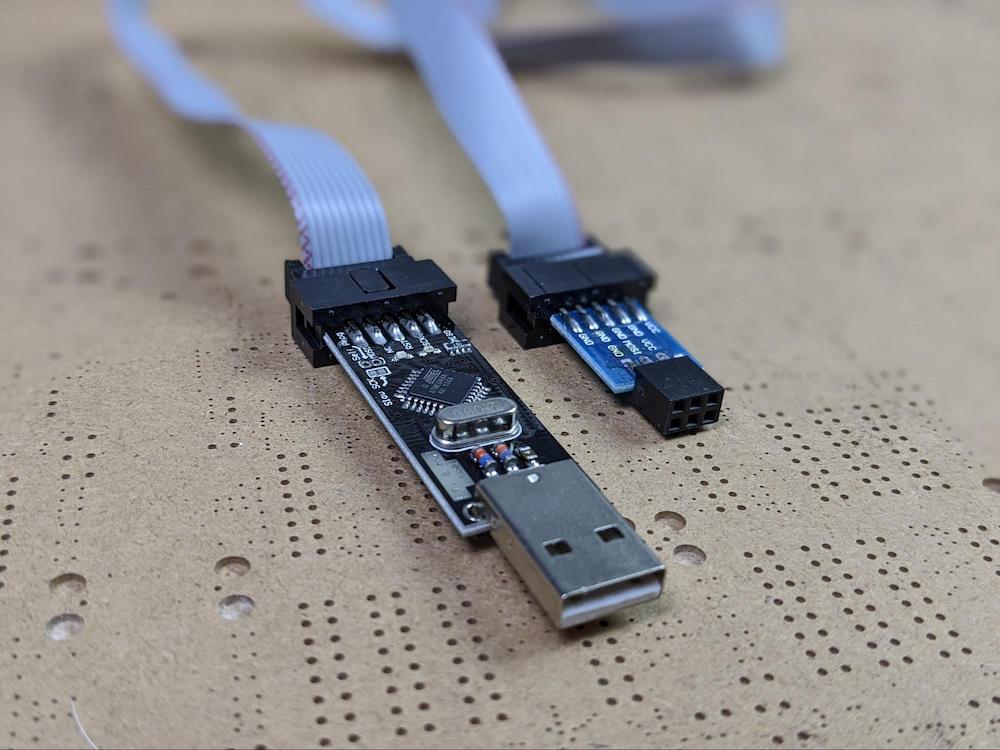
To program the microcontroller, we need a USB ISP AVR programmer, which is a tool used to flash the bootloader and program code to the ATmega328p. These tools can be obtained from any number of sources.
The only requirement for this project is that your USB AVR programmer includes a cable or adapter for using a six-pin ISP header like the one on the robot’s arm.
This USB ASP programmer has an adapter that allows it to interface with a six-pin programming header.
For the sake of aesthetics, we did not add any pins to the ISP header on the Maker Pro robot PCB. Instead, in order to connect the USB ASP programmer to the board, we will use a nifty little part called a pogo pin. A pogo pin is a spring-loaded pin that can be used to make temporary electrical connections.
Pogo Pin Demo
Take six pogo pins and insert them into the six-pin header on the USB ASP programmer. This little mechanism will allow us to temporarily connect a computer to the Maker Pro robot PCB for programming.
The pogo pins allow the USB ASP programmer to be temporarily connected to the PCB without requiring headers to be soldered to the board.
Download the Code
Next up, download the code for the project and open it (or copy/paste) with the Arduino IDE.
/*
   Project:  Maker Pro robot PCB badge
   Published on Maker Pro
   Author:  Scott Hatfield (Toglefritz)
*/

// NEOPIXEL SETUP //

// Include the Adafruit NeoPixel library
#include <Adafruit_NeoPixel.h>

#define PIN 6   // The LEDs are all controlled from pin 6

// There are a total of five LEDs on the Maker Pro robot badge: one on the antenna,
// one on each eye, and two on the wrench
#define NUMPIXELS 5   // There are five LEDs

// Set up the NeoPixel library
Adafruit_NeoPixel pixels(NUMPIXELS, PIN, NEO_GRB + NEO_KHZ800);

// The LEDs are all in a single 'strip' with the index on the strip used to activate
// each LED individually
#define LEYE 0
#define REYE 1
#define WTOP 2
#define WBOT 3
#define ANT 4

// Create some color variables to use with the LEDs
uint32_t red = pixels.Color(255, 0, 0);
uint32_t off = pixels.Color(0, 0, 0);

// BUTTONS SETUP //

#define NEXT 15
#define PREV 7

// EINK DISPLAY SETUP //

// Include the libarries necessary to control the display
#include <Adafruit_GFX.h>    // Core graphics library
#include "Adafruit_EPD.h"    // Hardware-specific library
#include <SD.h>

// eInk display connections

#define EPD_CS     10
#define EPD_DC      9
#define SRAM_CS     8
#define EPD_RESET   5
#define EPD_BUSY    -1 // Do not use a pin (will wait a fixed delay)
#define SD_CS       4

// Set up the display
Adafruit_SSD1608 display(200, 200, EPD_DC, EPD_RESET, EPD_CS, SRAM_CS, EPD_BUSY);
#define BUFFPIXEL 20


// SKETCH VARIABLES  //

long progTime = 0;    // A variable for tracking the time since the program started running via millis() method

// Antenna LED variables
int prevBlink = 0;   // A variable for tracking the last time the antenna LED blinked
long blinkInterval = 2000;    // The LED on the top of the antenna blinks on a random interval between two and seven seconds
const int blinkDuration = 200;    //  This variable determines how long each antenna blink lasts

// Eye LED variables
int eyeR = 0;   // The eye LED red channel
int eyeG = 204;   // The eye LED green channel
int eyeB = 193;   // The eye LED blue channel

// Wrench LED variables
int mode = 1;   // A variable for tracking what animation to use for the wrench LEDs (1 = rainbow cycle, 2 = color flash, 3 = split rainbow)
float wrenchRainbowColor = 1.00;    // A variable for the color for the wrench LEDs
int wrenchFlashColor = 1;   // A variable for the color for the wrench LEDs
int flashInterval = 1000;   // The interval for flashing the LEDs
int prevFlash = 0;    // The time the LEDs last flashed
bool flashState = true;    // A boolearn for turning the LEDs on and off

// eInk display variables
int prevDispChange = 0;   // A variable for tracking the last time the image on the eInk display was changed
int totalQRimages = 3;    // The total number of QR code images stored on the SD card
int imageSelector = 1;  // An image used to select which image to display

void setup() {
  // Set up the LEDs
  pixels.begin();   // Initialize NeoPixel object
  pixels.clear();   // Set all pixel colors to 'off' to start
  pixels.setBrightness(50);   // The LEDs do not need to be super bright

  // Set pin modes for the buttons
  pinMode(NEXT, INPUT);
  pinMode(PREV, INPUT);

  // Initialize the SD card
  SD.begin(SD_CS);

  display.begin();
  // Reset the display
  display.clearBuffer();
  // Rotate the display to show the QR codes the right side up
  display.setRotation(3);

  // Display the first image
  bmpDraw("/qrcode1.bmp",0,0);
}

void loop() {
  // Most of the LED-related functions are timing based. Therefore, on each loop, get the current program time.
  progTime = millis();

  // ANTENNA LED //

  // The LED on the antenna blinks at random intervals
  // If it has been at least the blink interval time since the last antenna blink, then blink the antenna
  if(progTime - prevBlink > blinkInterval) {
    // Turn the antenna LED on
    pixels.setPixelColor(ANT, red);
    // Update the previous blink time
    prevBlink = millis();
    // Get a new blink interval
    blinkInterval = random(2000, 7000);   // Get a random interval between five and seven seconds
  }
  // If the antenna LED has been on for at least the blink duration, turn it back off again
  else if(progTime - prevBlink > blinkDuration) {
    pixels.setPixelColor(ANT, off);
  }

  // EYE LEDS //

  // The eye LEDs glow a random color that changes each time the NEXT or PREV buttons are pressed
  pixels.setPixelColor(LEYE, eyeR, eyeG, eyeB);
  pixels.setPixelColor(REYE, eyeR, eyeG, eyeB);

  // WRENCH LEDS //

  // The wrench LEDs have three possible modes that change each time the NEXT or PREV buttons are pressed
  // If mode = 1, do rainbow cycle animation
  if(mode == 1) {
    if(wrenchRainbowColor < 255) {
      wrenchRainbowColor = wrenchRainbowColor + 0.01;
    }
    else {
      wrenchRainbowColor = 0;
    }

    pixels.setPixelColor(WTOP, Wheel(wrenchRainbowColor));
    pixels.setPixelColor(WBOT, Wheel(wrenchRainbowColor));
  }

  // If mode = 2, do color alternate flash
  else if(mode == 2) {
    // If flashState is true, turn on the LEDs
    if(flashState) {
      pixels.setPixelColor(WTOP, Wheel(wrenchFlashColor));
      pixels.setPixelColor(WBOT, Wheel(wrenchFlashColor));
    }
    // If flashState is false, turn off the LEDs
    else {
      pixels.setPixelColor(WBOT, off);
      pixels.setPixelColor(WTOP, off);
    }

    // If it has been at lesat the cycle interval since the last cycle, swtich the LEDs and increment the color
    if(progTime - prevFlash > flashInterval) {
      flashState = !flashState;   // Switch the LED state
      prevFlash = millis();   // Update the previous flash time

      // If the cycle color is under or equal to 250, increase the color by a value of 5
      if(wrenchFlashColor <= 250) {
        wrenchFlashColor = wrenchFlashColor + 5;
      }
      // Otherwise, set the color back to zero
      else {
        wrenchFlashColor = 0;
      }
    }
  }

  // Otherwise, if mode = 3, do split rainbow animation
  else {
    if(wrenchRainbowColor < 255) {
      wrenchRainbowColor = wrenchRainbowColor + 0.01;
    }
    else {
      wrenchRainbowColor = 0;
    }

    pixels.setPixelColor(WTOP, Wheel(wrenchRainbowColor));
    pixels.setPixelColor(WBOT, Wheel(wrenchRainbowColor + 127));
  }

  // Update the LEDs
  pixels.show();

  // BUTTONS //

  // If either button is pressed, update the LEDs
  if(digitalRead(NEXT) == HIGH || digitalRead(PREV) == HIGH) {
    // Change the eye color
    int colorSelect = random(0,10);

    switch(colorSelect) {
      case 0:
        eyeR = 0;
        eyeG = 204;
        eyeB = 193;
      break;
      case 1:
        eyeR = 11;
        eyeG = 118;
        eyeB = 217;
      break;
      case 2:
        eyeR = 11;
        eyeG = 180;
        eyeB = 227;
      break;
      case 3:
        eyeR = 11;
        eyeG = 227;
        eyeB = 155;
      break;
      case 4:
        eyeR = 11;
        eyeG = 217;
        eyeB = 90;
      break;
      case 5:
        eyeR = 213;
        eyeG = 21;
        eyeB = 178;
      break;
      case 6:
        eyeR = 153;
        eyeG = 128;
        eyeB = 15;
      break;
      case 7:
        eyeR = 255;
        eyeG = 37;
        eyeB = 25;
      break;
      case 8:
        eyeR = 204;
        eyeG = 70;
        eyeB = 0;
      break;
      case 9:
        eyeR = 232;
        eyeG = 12;
        eyeB = 84;
      break;
    }

    // Change the wrench LED mode
    if(mode < 3) {
      mode++;
    }
    else {
      mode = 1;
    }

    // The eInk display must be limited to updating at most once ever 180 seconds to avoid permenant
    // damage to the display. Therefore, before changing the image, check to make certain that at least
    // 180 seconds have passed since the last change.
    if(progTime - prevDispChange > 180000) {
    // If it was the next button that was pressed, go the next image
    if(digitalRead(NEXT) == HIGH) {
      if(imageSelector < 3) {
        imageSelector++;    // Increment the image selector
      }
      else {
        imageSelector = 1;
      }
    }
    // Otherwise, if the previous button was pressed, go the the previous image
    else {
      if(imageSelector > 1) {
        imageSelector--;    // Deincrement the image selector
      }
      else {
        imageSelector = 3;
      }
    }

    switch (imageSelector) {
      case 1:
        bmpDraw("/qrcode1.bmp",0,0);
        break;
      case 2:
        bmpDraw("/qrcode2.bmp",0,0);
        break;
      case 3:
        bmpDraw("/qrcode3.bmp",0,0);
        break;
     }

    // Update the previous display change time
    prevDispChange = millis();
  }
}
}

// Wheel() is a helper function to get colors from single values between 0 and 255
// Input a value 0 to 255 to get a color value.
// The colours are a transition r - g - b - back to r.
uint32_t Wheel(byte WheelPos) {
    WheelPos = 255 - WheelPos;
    if(WheelPos < 85) {
        return pixels.Color(255 - WheelPos * 3, 0, WheelPos * 3);
    }
    else if(WheelPos < 170) {
        WheelPos -= 85;
        return pixels.Color(0, WheelPos * 3, 255 - WheelPos * 3);
    }
    else {
        WheelPos -= 170;
        return pixels.Color(WheelPos * 3, 255 - WheelPos * 3, 0);
    }
}

// This function opens a Windows Bitmap (BMP) file and
// displays it at the given coordinates.  It's sped up
// by reading many pixels worth of data at a time
// (rather than pixel by pixel).  Increasing the buffer
// size takes more of the Arduino's precious RAM but
// makes loading a little faster.  20 pixels seems a
// good balance.
void bmpDraw(char *filename, int16_t x, int16_t y) {

  display.clearBuffer();

  File     bmpFile;
  int      bmpWidth, bmpHeight;   // W+H in pixels
  uint8_t  bmpDepth;              // Bit depth (currently must be 24)
  uint32_t bmpImageoffset;        // Start of image data in file
  uint32_t rowSize;               // Not always = bmpWidth; may have padding
  uint8_t  sdbuffer[3*BUFFPIXEL]; // pixel buffer (R+G+B per pixel)
  uint8_t  buffidx = sizeof(sdbuffer); // Current position in sdbuffer
  boolean  goodBmp = false;       // Set to true on valid header parse
  boolean  flip    = true;        // BMP is stored bottom-to-top
  int      w, h, row, col, x2, y2, bx1, by1;
  uint8_t  r, g, b;
  uint32_t pos = 0, startTime = millis();

  if((x >= display.width()) || (y >= display.height())) return;

  // Open requested file on SD card
  if ((bmpFile = SD.open(filename)) == (int)NULL) {
    Serial.print(F("File not found"));
    return;
  }

  // Parse BMP header
  if(read16(bmpFile) == 0x4D42) { // BMP signature
    Serial.print(F("File size: ")); Serial.println(read32(bmpFile));
    (void)read32(bmpFile); // Read & ignore creator bytes
    bmpImageoffset = read32(bmpFile); // Start of image data
    Serial.print(F("Image Offset: ")); Serial.println(bmpImageoffset, DEC);
    // Read DIB header
    Serial.print(F("Header size: ")); Serial.println(read32(bmpFile));
    bmpWidth  = read32(bmpFile);
    bmpHeight = read32(bmpFile);
    if(read16(bmpFile) == 1) { // # planes -- must be '1'
      bmpDepth = read16(bmpFile); // bits per pixel
      Serial.print(F("Bit Depth: ")); Serial.println(bmpDepth);
      if((bmpDepth == 24) && (read32(bmpFile) == 0)) { // 0 = uncompressed

        goodBmp = true; // Supported BMP format -- proceed!
        Serial.print(F("Image size: "));
        Serial.print(bmpWidth);
        Serial.print('x');
        Serial.println(bmpHeight);

        // BMP rows are padded (if needed) to 4-byte boundary
        rowSize = (bmpWidth * 3 + 3) & ~3;

        // If bmpHeight is negative, image is in top-down order.
        // This is not canon but has been observed in the wild.
        if(bmpHeight < 0) {
          bmpHeight = -bmpHeight;
          flip      = false;
        }

        // Crop area to be loaded
        x2 = x + bmpWidth  - 1; // Lower-right corner
        y2 = y + bmpHeight - 1;
        if((x2 >= 0) && (y2 >= 0)) { // On screen?
          w = bmpWidth; // Width/height of section to load/display
          h = bmpHeight;
          bx1 = by1 = 0; // UL coordinate in BMP file

          for (row=0; row<h; row++) { // For each scanline...

            // Seek to start of scan line.  It might seem labor-
            // intensive to be doing this on every line, but this
            // method covers a lot of gritty details like cropping
            // and scanline padding.  Also, the seek only takes
            // place if the file position actually needs to change
            // (avoids a lot of cluster math in SD library).
            if(flip) // Bitmap is stored bottom-to-top order (normal BMP)
              pos = bmpImageoffset + (bmpHeight - 1 - (row + by1)) * rowSize;
            else     // Bitmap is stored top-to-bottom
              pos = bmpImageoffset + (row + by1) * rowSize;
            pos += bx1 * 3; // Factor in starting column (bx1)
            if(bmpFile.position() != pos) { // Need seek?
              bmpFile.seek(pos);
              buffidx = sizeof(sdbuffer); // Force buffer reload
            }
            for (col=0; col<w; col++) { // For each pixel...
              // Time to read more pixel data?
              if (buffidx >= sizeof(sdbuffer)) { // Indeed
                bmpFile.read(sdbuffer, sizeof(sdbuffer));
                buffidx = 0; // Set index to beginning
              }
              // Convert pixel from BMP to EPD format, push to display
              b = sdbuffer[buffidx++];
              g = sdbuffer[buffidx++];
              r = sdbuffer[buffidx++];

              uint8_t c = 0;
              if ((r < 0x80) && (g < 0x80) && (b < 0x80)) {
                 c = EPD_BLACK; // try to infer black
              } else if ((r >= 0x80) && (g >= 0x80) && (b >= 0x80)) {
                 c = EPD_WHITE;
              } else if (r >= 0x80) {
                c = EPD_RED; //try to infer red color
              }

              display.writePixel(col, row, c);
            } // end pixel
          } // end scanline
        } // end onscreen
        display.display();
        Serial.print(F("Loaded in "));
        Serial.print(millis() - startTime);
        Serial.println(" ms");
      } // end goodBmp
    }
  }

  bmpFile.close();
  if(!goodBmp) Serial.println(F("BMP format not recognized."));
}

// These read 16- and 32-bit types from the SD card file.
// BMP data is stored little-endian, Arduino is little-endian too.
// May need to reverse subscript order if porting elsewhere.

uint16_t read16(File &f) {
  uint16_t result;
  ((uint8_t *)&result)[0] = f.read(); // LSB
  ((uint8_t *)&result)[1] = f.read(); // MSB
  return result;
}

uint32_t read32(File &f) {
  uint32_t result;
  ((uint8_t *)&result)[0] = f.read(); // LSB
  ((uint8_t *)&result)[1] = f.read();
  ((uint8_t *)&result)[2] = f.read();
  ((uint8_t *)&result)[3] = f.read(); // MSB
  return result;
}
The code is heavily commented on if you want to understand exactly how it works but the overall functionality is not too complex. There are essentially two major parts: the code that controls the LEDs, and the code that manages the eInk display.
Controlling the Five LEDs
A chunk of the code is dedicated to controlling the five LEDs on the PCB. The robot’s eye LEDs choose a random color to glow each time the NEXT or PREV buttons are pressed.
The LED at the top of the antenna blinks red at random intervals. The two LEDs on the wrench also change each time the QR code changes; they can cycle colors, flow through a rainbow of colors, or individually flow through a rainbow of colors.
Wrench LED Animation 1 Video
Wrench LED Animation 2 Video
Displaying QR Codes
The other major functionality is displaying QR codes on the eInk display. The QR codes themselves are loaded from image files stored on the SD card installed on the back of the eInk display (more on that later).
The QR code allows others to scan the code and view your articles on Maker Pro. On the robot’s legs, there is a NEXT and a PREVIOUS button to change the QR code. In order to avoid damage to the eInk display, the maximum frequency with which the QR codes can be changed is once every three minutes.
Flash the Bootloader
Before code can be uploaded to the ATmega328p onboard the Maker Pro robot PCB, we will need to flash the Arduino bootloader onto the chip.
The Arduino bootloader is a little program that runs on the microcontroller that allows it to understand code being uploaded from the Arduino IDE. When you purchase an Arduino board, it comes pre-flashed with the Arduino bootloader. In this case, though, our ATmega328p is blank. Before we can upload code, we will need to put the bootloader onto the chip, a process called burning the bootloader. This will only need to be done once.
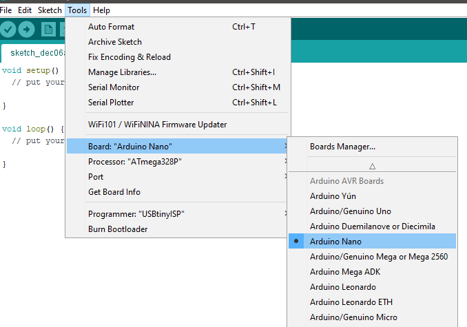
First, we need to set up the Arduino IDE to connect with the Maker Pro robot badge. First, from the Tools > Board: menu, select Arduino Nano. We make this selection because the Arduino Nano also uses an ATmega328p.
From the Tools menu, under Board:, select Arduino Nano.
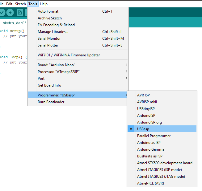
Then, in Tools > Programmer: select USBasp.
From the Tools menu, under Programmer:, select USBasp.
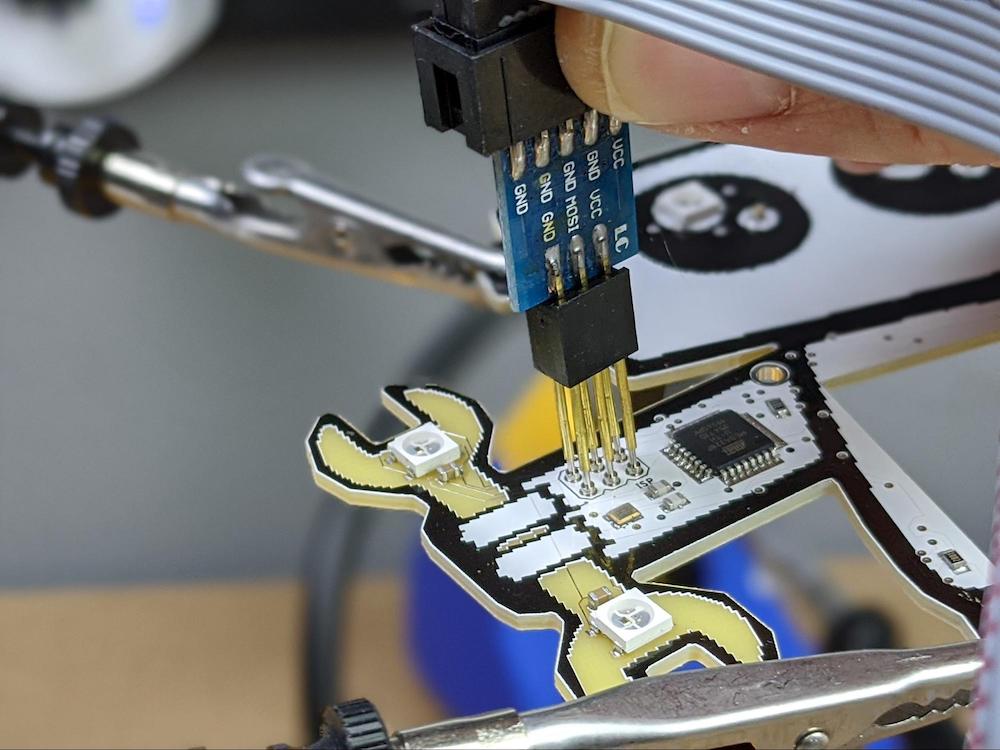
Now, to flash the Arduino bootloader onto the ATmega328p, we first need to connect the USB ASP programmer to the Maker Pro robot PCB.
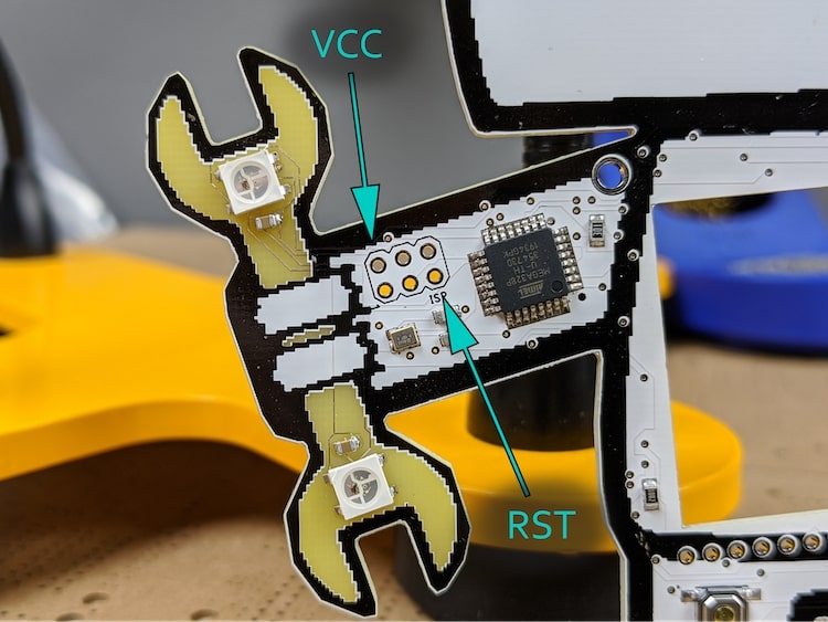
If you take a look at the USB ASP programming tool into which we placed the pogo pins, you will find a pin labeled RST. The USB ASP programming pins should be oriented so that this RST pin connects to the pin just above the ISP label on the board’s ISP header, as indicated in the photo below.
Correct placement of the USB ASP programming pins.
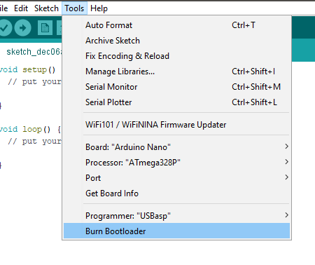
Then, with the USB ASP programmer connected to the Maker Pro robot PCB via pogo pins, select Tools > Burn Bootloader in Arduino IDE.
Burning the bootloader should only take a moment and you will get a success message at the bottom of the IDE once the process is complete. Just make certain to keep the USB ASP programmer in place until the bootloader is finished burning onto the microcontroller or you could risk bricking the chip.
With the USB ASP programmer in place, select Tools > Burn Bootloader.
Upload the Code
Once the bootloader has been successfully flashed onto the ATmega328p, we can upload the actual code that will run the badge.
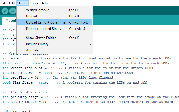
Normally, you would simply press the Upload button in the Arduino IDE toolbar, however, this functionality requires a USB to serial adapter on the PCB, which our Maker Pro robot badge lacks. Instead, with the USB ASP programmer still connected to the board, go to Sketch > Upload Using Programmer.
To upload code using the USB ASP programmer, select Sketch > Upload Using Programmer.
Just like when you upload code via a USB connection, as you do with Arduino board, the Arduino IDE will verify and compile the sketch, then display a “Done uploading” message when the processes finish.
Review of Progress and Next Steps
Directly programming an ATmega328 microcontroller is a bit different from programming an Arduino board — even one using the same microcontroller. There are several ways to program microcontrollers after they have been assembled into a PCB.
For this project, we used one of the most common methods of programming microcontrollers as part of the electronics manufacturing process: using an ISP header on the Maker Pro robot PCB.
At this point, there is only one task left to finish up the project: creating the QR codes that will be displayed on the eInk module.