Learn how the inter-integrated circuit (I2C) communications protocol works and how it can be implemented in your design.
This article serves as an introduction to getting your devices to talk with each other using the I2C protocol.
If you’re working with Arduino, Raspberry Pi, or any other embedded device, you’ll most likely use I2C when you’re using sensors, RTC (real-time clocks), servo motors, and more. Many times, you’ll have a software library published online for your use.
While the software libraries published online are handy, it's also important to understand how the I2C protocol works so you can go beyond using libraries to interface your device. Having this knowledge gives you the freedom to choose from a plethora of other I2C devices available and to bring your prototype into a custom design.
How Does I2C Work?
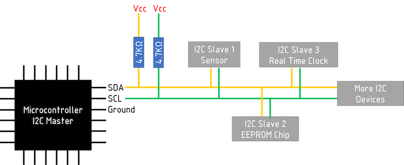
For I2C to work, the system requires one device to be set as a master to control the flow of information. The rest of the devices are set as slave devices. The slave devices receive commands from the master and send information at the request of the master.
An example circuit utilizing I2C.
Each slave device in the I2C bus has its own unique address which is 8 bits long. The first 7 bits are the device’s unique address and the last bit is 1 for write and 0 for read.
Data in I2C is sent in chunks of 8 bits (1 byte). I2C controls the flow of data by using a “handshake” process. If the master sends 1 byte, it waits for the slave device to respond back with 1 bit also known as an acknowledgement bit before the master sends the next byte of data and vice versa when a master reads a byte of data from the slave, the master sends an acknowledgment bit to the slave before reading the next byte of data.
Visualizing I2C as Teacher and Student
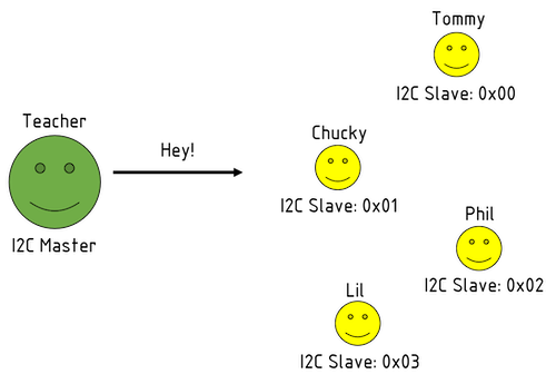
In my experience, I found that an easy way to visualize I2C is to imagine a classroom with the I2C master as the classroom teacher and the I2C slaves as the students in the class.
Picture your I2C master as the teacher and each I2C slave as a student.
The I2C master initiates communication by sending 1 start bit.
The I2C master sends out one start bit.
The I2C Master calls for the slave device by writing the slave’s 7-bit address with a write bit to send a command.
Since the I2C devices are on the same bus, they will all see the incoming command, but only the device being called by the master will respond.
The I2C master calls out to a specific I2C slave using a 7-bit address.
The master receives an acknowledgment from the slave before sending the next byte of data which is the command.
The slave called by the 7-bit address responds to the master.
The I2C master will now send the command to the I2C slave device.
The master sends a specific command to the slave.
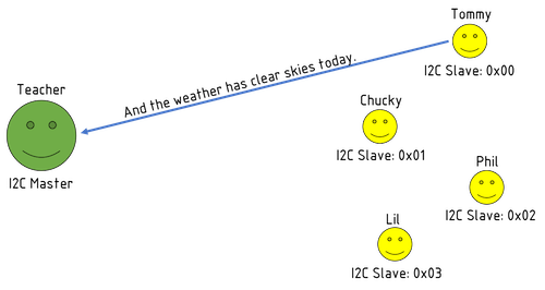
The I2C slave device starts to send data to the master.
The slave answers the master's request.
The I2C slave waits for an acknowledgement from the master before sending the next byte of data.
The master acknowledges the first bit of data before the slave continues delivering information.
The I2C slave device sends the next byte of data to the master.
The slave now sends the next byte of data.
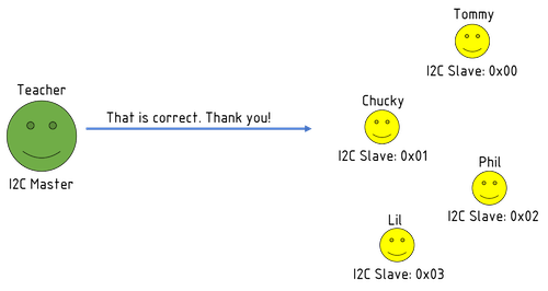
When the I2C master gets the last byte of data from the I2C slave, it ends the communication.
After receiving the data, the master ends the communication.
This same exchange can happen between the I2C master and any of the I2C slaves.
Considerations When Implementing I2C in Your Design
Implementation of I2C in your own designs requires you to remember a few crucial aspects as you begin.
Read the Manual
Always read the I2C section for whatever microcontroller that you are using. Look at the I2C sequence to read and write to the device.
List all the possible commands for the device and store them in a constant. For example:
#define READ_SENSOR 0x54
Or
const int READ_SENSOR = 0x54;
Have a Device Ready to Test I2C Routines
If you’re moving away from Arduino and writing your own code in a different platform such as Atmel Studio, have a device that already works with Arduino and use it to test the I2C routines that you write. This will make troubleshooting easier for you in the long run.
Troubleshooting I2C Designs
Once you have your design built and running on I2C communication, there may be cases where the communication is failing. If this occurs, there are ways to check your design.
Use a Logic Analyzer
A logic analyzer is one of the most useful tools to have when it comes to troubleshooting any serial communications because it shows you all the details on the raw communication occurring between each device.
The logic analyzer captures packets of data for a certain specified time period so be sure to create a test mode in your code so you can start the specific part of the communication that you want to analyze. A logic analyzer is pricey, but worth the investment.
Check for Duplicate Addresses
The device datasheet specifies the address for the device that you’re using and how to change the address. However, if the device does not allow for address modification, you won’t be able to add the same device on the I2C bus.
Ways around this issue include using a second available I2C port or creating a software I2C port on the I2C master.
Additional I2C Resources