This article introduces the most commonly-used connectors and the role each type of connector plays in design.
Circuits are made up of electronic components and can be created to do just about anything. However, circuits always need some kind of input or output from an external device whether it be a power supply, switch, display, motors, or even a cup warmer heat pad!
To connect to external devices circuits often use connectors, which provide an easy way to form removable connections. Connectors come in many varieties and since there are so many different types of connectors only the most common ones will be covered here. Connectors can have a number of identifiers making them easy to spot on the circuit. The identifiers that are used include J (for jumper), P (for pin), and CON.
PCB Interconnectors
PCB interconnectors connect two different PCBs together and are available as through-hole and SMD.
The through-hole variety involves pin headers and pin sockets that interlock with each other and are the most common type of interconnect used by hobbyists. They are easily identified by their large pin headers and their pin sockets have thick black bodies with matching holes.
A single-row pin header (left) and a single-row pin socket (right). Images courtesy of Oomlout [CC BY-SA 2.0].
The SMD PCB interconnectors have bent legs that are soldered to the surface of the PCB.
A dual-row SMD connector. Image courtesy of Mouser.
The through-hole connectors offer the strongest type of interconnect especially when used on a through-hole plated PCB but SMD connectors can be more fragile, and through-hole connectors offer the strongest type of interconnect especially when used on a through-hole plated PCB.
PCB interconnectors are not used much in the industry because smaller connector types are more convenient.
Edge Connectors
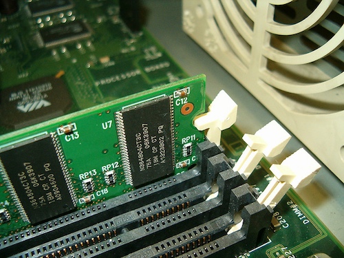
Edge connectors, like PCB interconnectors, are used to connect one PCB to another PCB. However, instead of using pins, edge connectors use the PCB edge.
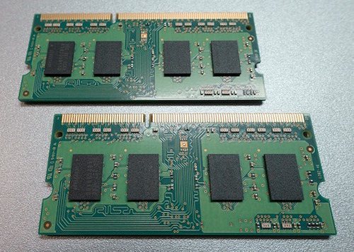
The PCB connecting to the main PCB has tinned gold contacts on its edge that, when inserted into an edge connector, makes contact with springs or contacts. Edge connectors are used in the PC industry with RAM sticks, graphics cards, and other devices as a means to connect to the main motherboard.
PCBs with tinned gold contacts on their edge [CC BY-SA 0.0].
Edge connectors offer an easy method for customizing devices and adding on plug-and-play features, but they are not without their faults. One problem with edge connectors is that both the edge connector itself and the contacts on the PCB can wear down—a common problem with retro game cartridges.
Terminal Blocks
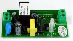
Terminal blocks are commonly found in situations involving large currents and the need for customization. They are often green and housed in a thick tough plastic casing.
Each contact point has a screw (often flat head), that is used to tighten the internal grip. To use a terminal block, the screw is turned counterclockwise to open the grip, the wire is inserted, and then the screw is tightened to grip the inserted wire. People may think that a really tight grip is good but that is far from true. A grip that is too tight can break the wire!
Terminal blocks are almost always used in electrical installations in buildings and are commonly found on PCBs involving mains electricity.
A Wi-Fi controllable AC switch with terminal blocks.
Ribbon Cable Connectors
Ribbon cables were incredibly popular in older designs—especially in computers using parallel interfaces with floppy controllers and hard drives.
These days, with buses becoming serial in nature (one data bit transmission), ribbon cables are losing popularity. However, ribbon connectors are still produced and can be useful for niche applications, to repair older equipment, and in designs that want to transmit parallel data. In commercial applications, ribbon connectors have mostly been replaced with flexible flat printed circuit connectors (which we'll touch on more next).
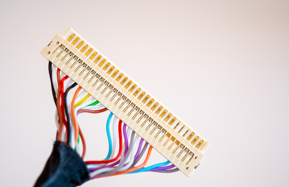
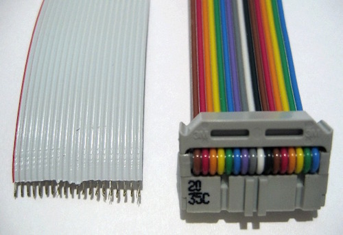
Ribbon cable connectors have tiny jaws that bite into the ribbon cable to make contact with the individual wires and the sockets for ribbon connectors are similar to pin headers.
Example of a ribbon cable's wires and end connector. Image courtesy of Heron [CC BY-SA 3.0].
FFC/FPC Connectors
Flat flexible cable (FFC) and flexible printed circuit (FPC) connectors are very common in modern electronics, as they can connect two devices with many wires without sacrificing space.
FFC/FPC connectors play an important role in two very different components, so it’s important to understand the difference between FFCs and FPCs. Flexible flat cables are simply a smaller version of ribbon cables and are often used in place of round cables for their flexible design when space is limited. Meanwhile, a flexible printed circuit is a complete circuit printed onto a flexible substrate. They are made of an orange plastic material with printed wires and are commonly found in devices that have displays, such as laptops, MP4 players, and camera modules.
FFC/FPC connectors are incredibly short and have a lock button to keep the cable in place.
An FPC cable on a GoPro, an FFC/FPC connector, and an FPC cable directly soldered onto a PCB.
FFC/FPC connectors play an important role in two very different components, so it’s important to understand the difference between FFCs and FPCs. Flexible flat cables are simply a smaller version of ribbon cables and are often used in place of round cables for their flexible design when space is limited. Meanwhile, a flexible printed circuit is a complete circuit printed onto a flexible substrate. They are made of an orange plastic material with printed wires and are commonly found in devices that have displays, such as laptops, MP4 players, and camera modules.
FFC/FPC connectors are incredibly short and have a lock button to keep the cable in place.
JST Connectors
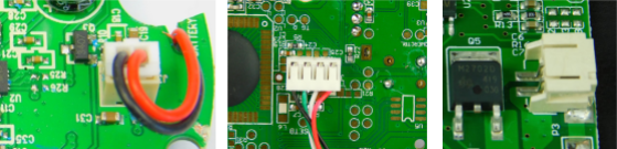
JST (Japan Solderless Terminal) connectors were originally designed and manufactured by JST Mfg Co but are now widely produced and used in modern electronics. They have found their way into many devices and are used for connecting devices such as batteries and speakers to PCBs.
These connectors are not suitable for reflow soldering and therefore are either wave- or hand-soldered at the factory.
Examples of JST connectors on PCBs.
BNC Connectors
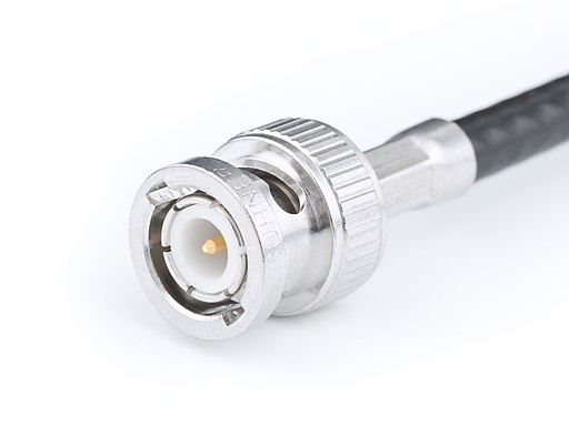
BNC (Bayonet Neill–Concelman) connectors involve a single central pin that is surrounded by a grounding shield. These connectors are used in situations where a signal needs to be protected from external sources. They are most commonly found on oscilloscopes and other test equipment but similar connector types can be found on aerial cables and in audio transmission lines.
BNC connectors have a twist and lock feature that prevents them from being pulled out unexpectedly and are generally quite expensive when compared to other connector types.