555 ICs are used in a variety of projects. Learn why they're important and how you can use them in your projects!
The 555 timer astable circuit is one of the most famous ICs in existence with its origins dating back to 1971. This tiny chip can be made to do a number of things and in this Maker Pro tutorial, we will see how a 555 IC can be used to make an astable oscillator – a circuit that continuously switches between two different states!
Required Hardware
- 555 IC
- 2 x 1kΩ resistor
- 1 x 100kΩ linear potentiometer
- 1 x 10uF Capacitor
- 1 x 100nF Capacitor
- 1 x 3mm LED
- Breadboard
- Power source (9V battery for example)
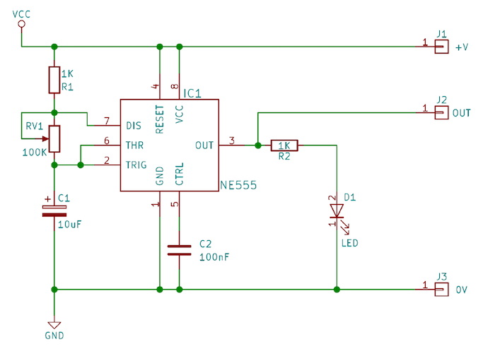
Schematic
What's Inside the 555 IC?
The 555 is an 8 pin IC that consists of two internal comparators, a flip-flop with an inverting output, output inverting buffer, a discharge transistor, and three resistors.
The three resistors all have equal values there is an interesting rumor among engineers is that the 555 gets its name from the 3 internal 5kΩ resistors. However, this is nothing more than a rumor with the 555 getting its name by coincidence.
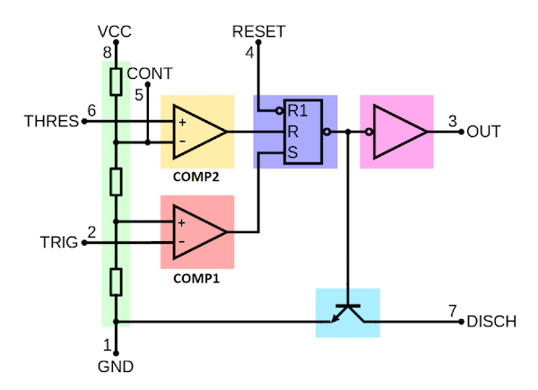
The internal schematic of the 555 can be seen below and will need to be consulted when understanding how the 555 astable oscillator works.
The internal schematic of the 555 astable oscillator.
The 555s internal flip-flop is controlled by two comparators that are connected to the potential divider chain made up by the three resistors.
In order for the flip-flop to be set and the output of the 555 to be VCC, the THRES pin needs to be lower than 2/3 VCC while the TRIG pin needs to be lower than 1/3 VCC.
In order for the flip-flop to be reset and the output of the 555 to be 0V, the THRES pin needs to be greater than 2/3 VCC and the TRIG pin needs to be greater than 1/3 VCC.
The Astable Circuit
To understand how this circuit works we first need to apply starting conditions as this is an oscillator. Therefore, we will assume our circuit initially has the following characteristics
- The capacitor C1 is completely discharged
- The internal flip-flop output is logical 0
- The 555 output pin is logical 1 (remember the output buffer is inverting)
The output of the flip-flop is initially logical 0 which means the discharge transistor is turned off. This means that C1 charges through RV1 and R1 which results in the voltage across C1 increasing.
The TRIG and THRES pins are connected together and measure the voltage across C1 and when the voltage across C1 goes beyond 2/3 VCC this causes the internal comparator (COMP2) to switch on which resets the flip-flop. When the flip-flop is reset the output of the flip-flop becomes logical 1 (remember, its an inverting flip-flop) and this turns on the discharge transistor.
At the same time, the output of the 555 becomes 0V as the inverting output buffer inverts the output of the flip-flop. Since C1 is connected to the discharge transistor through RV1 the capacitor C1 begins to discharge.
As C1 discharges the voltage across it eventually falls below 1/3 VCC and when this happens the internal comparator COMP1 switches on. When this happens, the internal flip-flop is turned on and this causes the output of the flip-flop to switch off. This turns off the discharging transistor and C1 begins to charge again. At the same time, the output of the 555 switches to VCC and therefore the circuits output switches between VCC and 0V creating an oscillator!
Building the 555 Astable Circuit
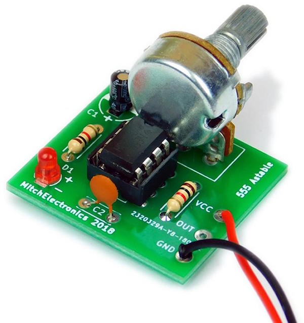
Building this circuit can be done using most (if not all) circuit construction techniques including stripboard, breadboard, bare parts, and even a custom PCB. However, in this project, we will use the MitchElectronics 555 Asatable Kit which includes all the parts needed to build the circuit including a PP3 connector for powering, a potentiometer so the output frequency can be adjusted, and a through-hole plated RoHS compliant PCB that allows the circuit to be used as a module as well as a stand-alone project.
What Can you Do With a 555 Astable Circuit?
The 555 astable circuit is a square wave oscillator that is capable of operating up to speeds of 1MHz and as such can be used for a wide range of applications.
One common use of the 555 is as a timer signal source that can provide timing pulses for counters and other timekeeping circuits while another example of the 555 astable circuit is a clock source for simple DIY computer builds (such as Z80 computers). 555 astable oscillators can also be used in musical instruments such as those seen in the Atari Punk project.
Examples of Projects Using a 555 Astable Circuit