Learn when a motor driver is necessary and how to choose one for your motor-controlled projects!
In robotics, there are different types of motors available: brushed motors, brushless motors, stepper motors, and servo motors. The motors can be controlled by various methods. Some motors can be directly connected to the power supply while others, like servo motors, need a signal from a controller to operate. When we need to control the motors using a controller, we need a motor driver.
What is a Motor Driver Circuit?
A motor driver circuit takes the low current signals applied by the controller and turns them into higher current signals that drive the motor. Basically, the motor driver acts as an interface between the motor and the control circuit. Motor drivers allow you to control a much larger load from a small signal. They can handle the high voltages and current where some motor work best.
A motor driver circuit consists of an IC or discrete JFETs that can handle high power. Motor driver ICs are current amplifier ICs and they act as a bridge between the controller and motor. Driver ICs include circuitry that help to interface between the H-bridge (which controls the motor) and the signals that tell the H-bridge how to control the motor. However different chips offer different interfaces. Some well-known motor driver ICs include the L293D and the L298N.
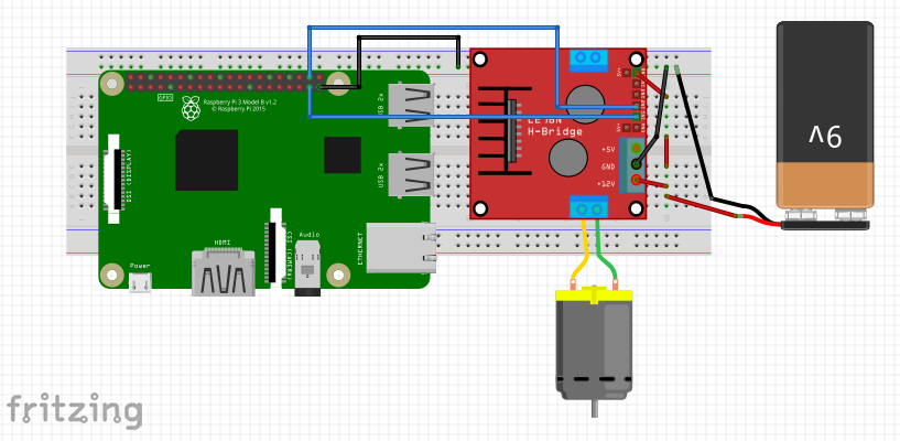
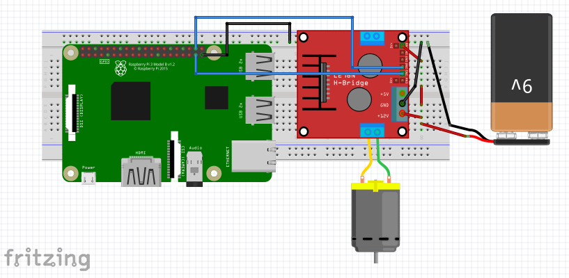
This schematic shows an example of where an L298 motor driver would fit into a project (in this case, using a Raspberry Pi and a DC motor)
H-bridge Circuit
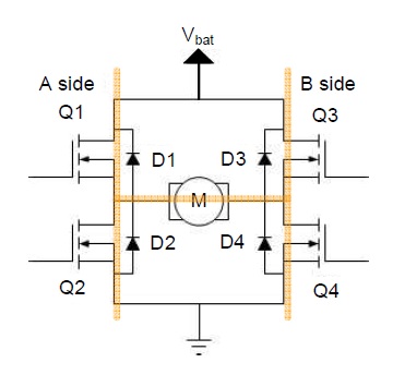
The H-bridge (shown in the image below) is a very simple circuit that allows a DC motor to go backward or forward — in other words, this circuit switches the polarity of a voltage applied to a load.
A basic H-bridge circuit diagram. The H-bridge is aptly named based on the familiar shape made by the two current paths. Image courtesy of All About Circuits.
When Q1 and Q4 are closed, Vbat is connected to the left terminal of the motor and GND to the right terminal which moves the motor in one direction. When Q2 and Q3 are closed, Vbat is applied to the right terminal of the motor and GND to the left which moves the motor in the other direction.
An H-bridge can be easily built with four transistors: two PNP and two NPN. PNP transistors are used for switching Vcc and NPN transistors are used for switching GND connection.
Selecting a Motor Driver
So how do you select the best motor driver for your project? The following are some important criteria to consider when selecting a motor driver.
Compatible Motors
The very first thing to look for when selecting a motor driver is the motor driver’s compatible list of motors.
Most motor drivers are compatible with brushless DC motors, geared motors, and stepper motors but some motor drivers are compatible for angle-based motors like servo motors. So it is necessary to choose the driver according to your motor.
Interface
You should coose the motor driver and its interface according to your application. Most motor drivers are compatible with Arduino and other TTL inputs. However, if you want to control the motor wirelessly, such as with Bluetooth control boards, then consider remote controllers.
Additionally, the number of channels must also be considered. When you need to control 16 motors with 16 external signals, then a 16-channel motor driver must be chosen if current and voltage are right.
Voltage and Current
Next, look at voltage and current handling capacity. Find a motor driver with a suitable voltage range according to your application.
Finding the right voltage range isn’t difficult. Motor drivers come in wide voltage ranges (like 4.5V – 36V). Also, finding a driver with enough current handling capacity is relatively simple, as there are drivers available in the market with high current handling capacity.
On-state Resistance
The current in the motor driver IC flows through on-state resistance of the bridge transistor. Therefore the high current will lead to power dissipation.
Power dissipation can be expressed asP=I2R, where R is the on-state resistance. Power dissipation happens in the form of heat. Driver IC operating at its peak current capacity very quickly increases the internal temperature and can cause a thermal shutdown.
Knowing this, you need to select an IC with plenty of current handling capacity and if there's any chance the IC will overheat, a mechanical heat sink must be incorporated.
However, many times, there's no space for such a thing on a PCB, so try to select an IC with lower on-state resistance for minimum power dissipation.


