Learn about how fast chargers work and how to design a fast charger for your smartphone.
Many manufacturers claim their charger products deliver fast charging speeds. Fast charging or quick charging is the term used by the marketing companies to market their chargers and show their capability of charging faster than the regular 5W chargers. In this article, we will mostly talk about fast charging related to smartphones.
Fast chargers are also possible for laptops, but for now, let's understand the electronics behind smartphone chargers and charge controllers.
How Does a Fast Charger Work?
To understand how a fast charger works, we first need to know how a lithium-ion battery is charged. Lithium-ion batteries are used in our smartphones and other electronic equipment, but they don't charge linearly. When a user connects the phone to the charger, the battery charges from 2V to a peak voltage of 4.2V.Charging in these batteries happens in two phases.
The first phase of charging is from 0%-50% of the charging. In this phase, the highest peak current and voltage are drawn to the battery and it remains constant throughout this phase. Thus, fast charging technologies are most effective when your battery is less than 50% full. After 50%, that current drawn towards the battery begins to fall. Therefore, the first 50% of your phone charges considerably faster.
The second phase begins when the battery has received most of its charge. The charge controller decreases the voltage and current drawn which prevents the phone from overheating ensuring the smartphone remains safe. This is why there is not much effect after 80% charging because it charges considerably slower than in phase one. For the amount of voltage and current to be passed, the charge controller circuit is used inside the phone. Moreover, there are temperature sensors, voltmeters inside monitoring during the battery ensuring their long term health.
The basic USB charger only sends 5V, 0.5A which is just 2.5W of power. Fast chargers like SuperCharger of Huawei supply 40W of power which is 10V, 4A. Some Chinese companies even hit up to 100W. Fast chargers have a common concept and that is supplying more power. But doesn’t more voltage harm our battery?
For this, fast chargers use a buck inverter, generally known as switch mode step down power supply which lowers the voltage and increases the current. More current will more rapidly fill up the battery with charges. Power remains the same if we do not consider the efficiency of the buck inverter.
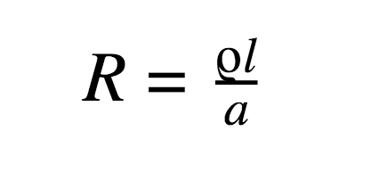
Another advantage of applying more power is taking note of power loss in transmission cables. More the length of cable more will be the resistance as per the formula:
According to Ohm’s law (V = IR), transmitting high voltage and lower current losses less power over the length of the cable.
Fast Charging Standards
There are two very well known types of fast chargers: USB power delivery and Qualcomm quick charge. There are others such as SuperCharger and TurboPower but even those are based on Qualcomm’s quick charge.
USB Power Delivery
USB power delivery is the fast charging standard published in 2012. This delivery system can be used in devices with a USB port. USB power delivery implements a data protocol to communicate between a smartphone and a charger. USB type C ports can be configured in fast charging modes at 1.5A or 3.0A for more power.
These chargers have a goal to become as standards and possibly reduce the e-waste by removing the need for chargers with various ratings. One more feature is that the delivery is bidirectional which means one can charge other peripherals using a smartphone.
Qualcomm Quick Charge
We discussed earlier that the amount of power to apply the battery is decided by the charge controllers inside the phone. Charge controllers are on-chip in Qualcomm processors, not all Qualcomm processors have charge controllers but smartphones that support fast charging needs to have this charge controller.
Fast Charger Circuit
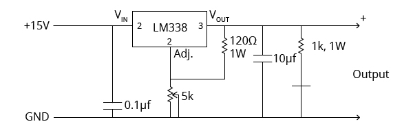
To make a fast charger, we need to stick to the concept of supplying more power. So we will create a power supply with output current up to 5A and the LM338 IC is perfect for this job. The LM338 voltage regulator IC can supply up to 7A of current at the output and the voltage range of 2 to 25 DC Volts.
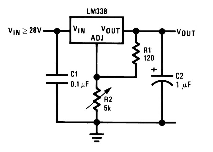
We will require two external resistors to adjust the output voltage. The typical LM338 circuit looks like this:
We are using 5kΩ of a variable resistor with a 120Ω resistor for adjusting the output voltage. Typically for an LM338, a 120Ω resistor is used for program resistor R1. The reference voltage for LM338 IC is 1.25V.
Two capacitors in the diagram are always used in application circuits as an input bypass capacitor and the capacitor at the output side for giving stability to the output current. We will get 2 – 15V DC at the output with maximum current up to 5A.
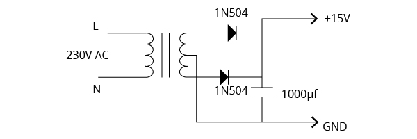
For supplying 15V to the circuit we have designed, we will use a 15-0-15V transformer and two diodes working a full-wave rectifier and a large capacitor for ripple-free DC voltage.
Success With the Fast Charger Circuit
So far we have seen how fast chargers work, how a lithium-ion battery is charged, some fast-charging standards, and looked at a design for a fast charger with the help of LM338 voltage regulator IC.
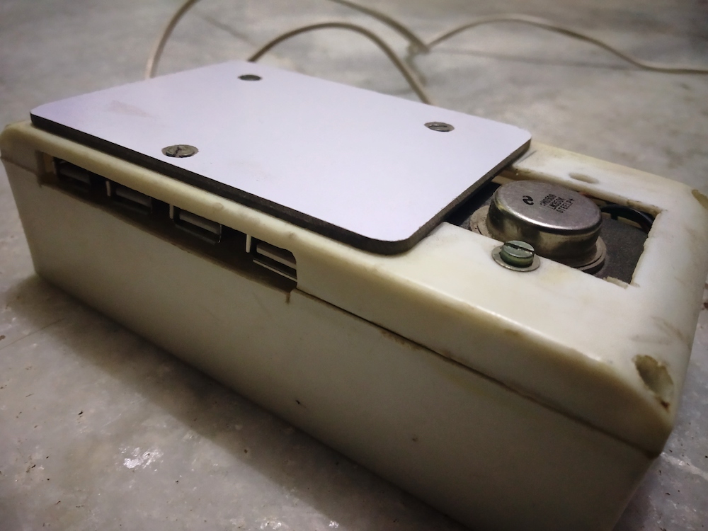
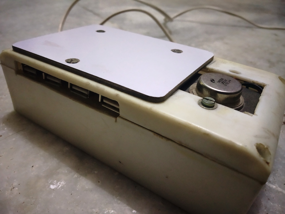
I successfully built this fast charger circuit and enclosed it in the switchboard getting handy power from USB ports at the output.
The fast charger I built for my phone.
