Learn how to build two circuits that will allow you to use an ATtiny microcontroller to take high-speed photos.
High-speed photography is a great indoor activity. It requires, however, a gadget to be used to trigger the camera and flash unit within a few milliseconds.
The gadget triggers the camera and this trigger can be light-sensing or sound-sensing devices. For example, if you are working with high-speed droplet photography, you should go with a light-triggered mechanism. If you want to photograph bullet bursting balloons, on the other hand, a sound-triggered device is a good choice.
A high-speed camera trigger consists of three main sections:
- The controller
- The delay
- Sensors
In this project, we use an ATtiny microcontroller as a controller unit. If you search for a DIY high-speed camera trigger, most of the results include construction using an Arduino board as the controller, instead. Arduino boards are often replaced with ATtiny in applications where you don’t need higher than few PWM pins. Here, we can use the ATtiny for a minimally-sized control circuit (and also, if one doesn't own an Arduino board, this is a cheap alternative circuit).
The ATtiny microcontroller we use here could be the ATtiny 13, 45, or 85. Each has five pins available for communication, e.g., PB0 to PB4.
Required Hardware
Here is what you'll need to be able to create this project.
For the first circuit:
- ATtiny 13/45/85 microcontroller
- 2 x BC 547 NPN transistors
- 3 x 10kΩ resistors
- IRF540 N channel MOSFET
- USB-to-TTL converter board
For the second circuit:
- ATtiny 13/45/85 microcontroller
- 10Ω resistor
- 2 x 10kΩ potentiometers
- LDR
- Laser diode
- Button
- 4N35 optocoupler
Software used:
Programming and Serial Communication with the ATtiny
Before we get into our circuits, it is important to know how to program the ATtiny IC.
For programming, you'll need a USB-to-TTL converter board.
The connections are as follows:
ATtiny.. .........................USB-to-TTL converter
Pin 6...............................Tx
Pin 5...............................Rx
Pin 4...............................GND
Pin 8...............................+5V
As noted above, the software we use here is the Arduino IDE, a free software program that is very mainstream.
After making the above connections and plugging the converter into your PC, you need to select the ATtiny board using the Tools>Board menu in the Arduino IDE. Now you can upload the necessary code.
If ATtiny microcontrollers are not in your list of boards, you'll need to add the following ATtiny libraries: https://github.com/SpenceKonde/ATTinyCore
Circuit 1
Our first circuit is based on trial and error. Here, you need to provide the delays to the circuit to get the desired results.
You'll need to play with timings here as there is no sensor attached and this circuit is very useful for manual operation.
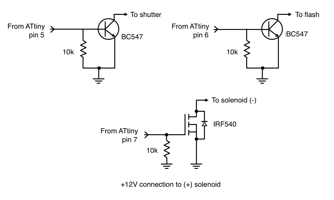
The circuit is built around an ATtiny microcontroller, two BC547 NPN transistors, and an IRF540 N-channel MOSFET. We use two PWM pins of the ATtiny—pin 5 and pin 6, referred to as PB0 and PB1, respectively. Both of these digital outputs control flash and camera.
Individual NPN transistors are used for flash and camera. Here we need to keep the ATtiny circuit connected to the computer to send the inputs of time delays. Moreover, we have added 10kΩ resistors and pull up and pull down resistors.
Power: The Optocoupler Circuit
To avoid blowing up our ATtiny, we arrange the MOSFET to power the solenoid. We provide external 12V power supply and the MOSFET is connected from solenoid (our load) to ground. When MOSFET GATE pin is high, the circuit is closed. So, the trigger here is simple as per our timings fed.
For very high voltages, an optocoupler is a good choice. Makers generally like to divide the optocoupler circuit into left and right sections.
On the left side, we provide our signal and input voltage. On the right side, we get the output voltage when the input signal is high.
The schematic for the first circuit
Connecting the Camera and Flash
Now, to connect the camera and flash with the circuit we use a jack. Our jack has three connecting points:
- Common ground
- One connection for flash
- One connection for shutter
Now you can temporarily connect or solder up the wires in camera and flash.
To feed the inputs, go to the serial monitor and enter comma-separated values like this: 270, 15. 45, 3.
So, the very first value is the time from the release of first flash fire (in ms). The second value is the time the solenoid should remain open (also in ms). The third value is the time for firing the flash for a second attempt (in ms). The fourth value is the number of times you’d like to repeat the same sequence.
For stop motion, the values of time delays are given in code.
int dropPin = 2; // pin that controls solenoid
int flashPin = 1;
int cameraPin = 0;
int inPin  = 7;
int val = 0;
int exposureCnt = 0;
int maxExposureCnt = 1;

boolean bArmCamera   = true; // true if camera shutter should be opened before drop execution
boolean bDirectFlash = true; // true if flash is directly connected to arduino

// stop motion settings
boolean bDoAnimation = false; // Do a timelapse sequence
int startI = 245;   // start time
int endI   = 260; // endst time
int incr = 1; // ms increment to take shots between start time and end time for animation
int dropDurationAnimation = 8; // ms time for solenoid open (Drop size)
int dropTime2Animation = 60; // ms time for when the second drop will be released (set to 0 for no second droplet)

// Laser-interrupt params
boolean bUseInterruptCode = false;
volatile boolean flag = false;
volatile int cnt = 0;

// Rotor laser-interrupt params
boolean bRotorMode  = false;
boolean bDisplayRPM = false;
volatile int rotorCnt = 0;
unsigned long rotorThen, rotorNow;
int timeBetweenPhotos = 1000; // ms


int delayTime = 0; // ms
//int dropTime  = 20; // ms
//int interDropTime = 100; //ms

int times[6] = {0, 20, 150, 0, 0, 0}; // trigger time, drop time, next drop time, next 3 are us additions to these times

boolean bExecuteDrop = false;

void setup() {
  Serial.begin(115200);
  pinMode(dropPin, OUTPUT);
  pinMode(flashPin, OUTPUT);
  pinMode(cameraPin, OUTPUT);
  pinMode(inPin, INPUT);
  //delayTime = startI;

  digitalWrite(cameraPin, LOW);
  //flag = false;

  // Test droplet
  executeDrop(20, 0);
  executeDrop(20, 150);

  if (bUseInterruptCode) {
    attachInterrupt(0, handleOptical, FALLING);
    if (!bDirectFlash) {
      prepCamera();
    }
  }

  if (bRotorMode) {
    attachInterrupt(0, handleRotor, FALLING);
    rotorThen = millis();
    rotorNow  = rotorThen;
    if (!bDirectFlash) {
      prepCamera();
    }
  }

  if (bDoAnimation) {
    times[0] = startI;
    //bExecuteDrop = true;
  }

}

void loop() {
  // Rotor laser-trigger code
  if (bRotorMode) {
    if (flag && (cnt < 1)) {
      detachInterrupt(0);
      executeDrop(times[1],times[2]); // drop time, delay for drop
      triggerFlash(times[0], times[3]); // delay time for flash, delay time us
      cnt++;

      if (bDoAnimation) {
        if (times[0] <= endI) {
          times[0] = times[0] + incr;
          cnt = 0;
        }
      }

      delay(timeBetweenPhotos);
      triggerCamera(0); // we're assuming a longer exposure here, something in the 1s range, and less than timeBetweenPhotos
      delay(500);
      attachInterrupt(0, handleRotor, FALLING);
      flag = false;
    }

    if (bDisplayRPM) {
      if (rotorCnt > 100) {
        detachInterrupt(0);
        rotorNow = millis();
        double rpm = 60.0 * 1000.0 * double(rotorCnt) / double(rotorNow - rotorThen);
        rotorCnt = 0;
        Serial.println(rotorNow);
        Serial.println(rotorThen);
        Serial.println(rpm);
        rotorThen = rotorNow;

        String output = "RPM: " + String(rpm, DEC);
        Serial.println(output);
        attachInterrupt(0, handleRotor, FALLING);
      }
    }
  }


  if (bDoAnimation && !bRotorMode) {
    if (times[0] <= endI) {
      times[0] = times[0] + incr;
      bExecuteDrop = true;
      delay(500);
    } else {
      bDoAnimation = false;
    }
  }


  if (bExecuteDrop) {
    int timeTrigger = times[0];
    int timeDrop    = times[1];
    int timeNext    = times[2];

    if (!bDirectFlash) {
      prepCamera();
    }

    if (bArmCamera) {
      prepCamera(); // arm the camera (assuming a shutter open time for 1-2 seconds)
      delay(500);
    }

    executeDrop(timeDrop, 0);
    executeDrop(timeDrop, timeNext);
    triggerFlash(timeTrigger - timeDrop*2 - timeNext); // timeTrigger should be measured from first drop point

    exposureCnt++; // increment the exposure cnt
    // Check to see if more photos should be taken or not
    if (exposureCnt >= maxExposureCnt) {
      bExecuteDrop = false;
      exposureCnt = 0;
    } else {
      delay(1000);
    }
  }

  //Old laser-trigger based code
  if (bUseInterruptCode) {
    if (flag) {
      detachInterrupt(0);
      triggerCamera(delayTime);
      cnt++;
      Serial.println("Triggered!");
      delay(500); // don't do anything for a 5sec
      //prepCamera();
      attachInterrupt(0, handleOptical, FALLING);
      flag = false;
    }
  } // interrupt code

  flag = false;

   // Check for an input
  if (Serial.available() > 0) {
    //cnt = 0;
    char buff[32];
    int returned = Serial.readBytesUntil('\n', buff, 32);
    buff[31] = 0;
    char *values = strtok(buff, ",");
    // Check data and convert to int
    if (returned == 0) {
      Serial.println("no valid data sent");
    } else {
      Serial.println("data recieved");
      int i = 0;
      while (values != NULL) {
        int val = atoi(values);
        Serial.println(val);
        times[i] = val;
        if (i == 3) {
          maxExposureCnt = val;
        }
        i++;
        values = strtok(NULL, ",");
      }
      // check if a valid number of inputs was found
      if (i == 4) {
        bExecuteDrop = true;
      }

      // laser interrupt code
      if ((i == 1) && (bUseInterruptCode || bRotorMode)) {
        delayTime = times[0];
        cnt = 0;
      }

      if ((i >= 3) && bRotorMode) {
        cnt = 0;
      }
    }
  } // if serial

} // loop

// Helpers


void delayExact(int timeMs, int timeUs) {
  timeMs=10;
  timeUs=60;
  if (timeMs > 0) {
    delay(timeMs);
  }
  if (timeUs > 0) {
    delayMicroseconds(timeUs);
  }
}

void executeDrop(int timeOn, int timeDelay) {
  timeDelay=245;
  if (timeDelay > 0) {
    delayExact(timeDelay, times[5]);
  }
  digitalWrite(dropPin, HIGH);
  delayExact(timeOn, times[4]);
  digitalWrite(dropPin, LOW);
}

// Function to trigger camera
void triggerCamera(int triggerTime) {
  if (triggerTime > 0) {
    delayExact(triggerTime, 0);
  }
  digitalWrite(cameraPin, HIGH);
  delay(10);
  digitalWrite(cameraPin, LOW);
}

// Function to trigger flashes
void triggerFlash(int triggerTime, int triggerTimeus) {
  if (triggerTime > 0) {
    delayExact(triggerTime, triggerTimeus);
  }
  digitalWrite(flashPin, HIGH);
  delay(10);
  digitalWrite(flashPin, LOW);
}

void triggerFlash(int triggerTime) {
  triggerFlash(triggerTime, 0);
}

void prepCamera() {
  digitalWrite(cameraPin,HIGH);
  delay(100);
  digitalWrite(cameraPin,LOW);
  delay(10);
}

// Interrupt handlers for laser-based code
void handleOptical() {
  flag = true;
}

void handleRotor() {
  rotorCnt++;
  flag = true;
  //Serial.println('!');
}
Circuit 2
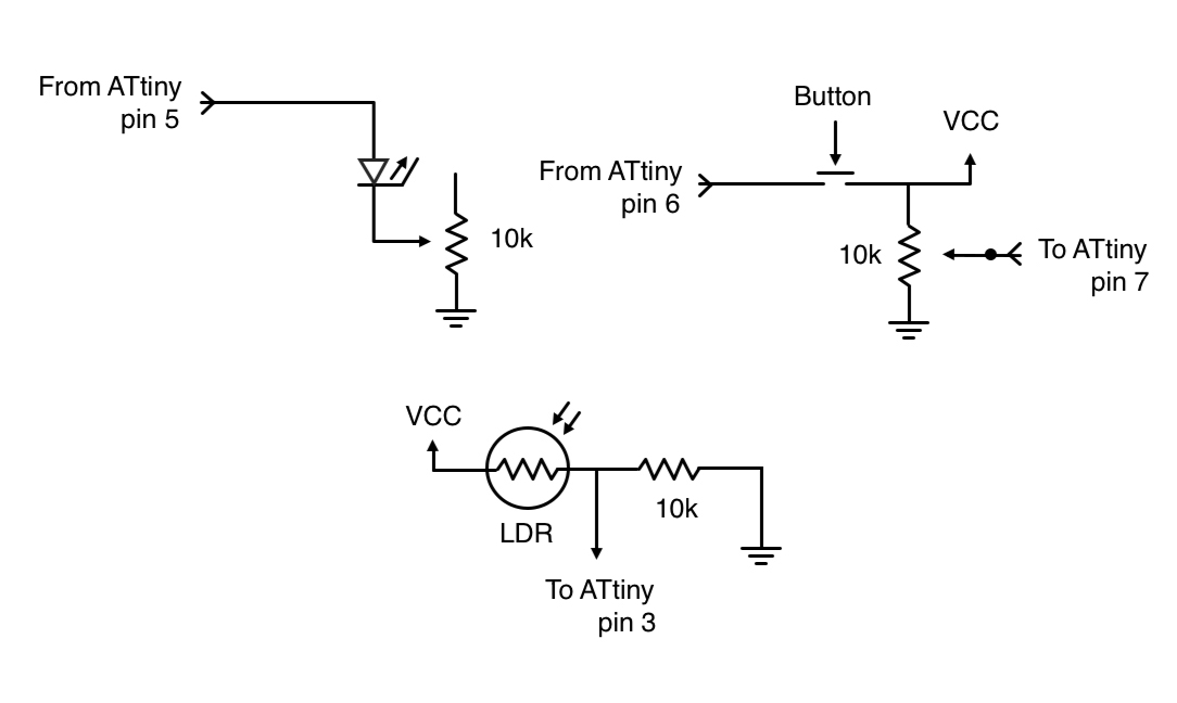
In our second circuit, we use the light sensor to act as the trigger—this can help us if you want to shoot for droplets splashing, etc.
Here, we use a simple laser diode and LDR arrangement to build our sensor circuit. Further, we add potentiometers to fine-tune for perfect delays.
This fine-tuning will allow you to capture drops sinking in liquid and splash back again.
The schematic for the second circuit
The connections here are simple.
We connect the analog input of the ATtiny to LDR such that when the droplet crosses the laser and LDR arrangement, we get the perfect shot as we set the accurate time delays by tuning the potentiometers.
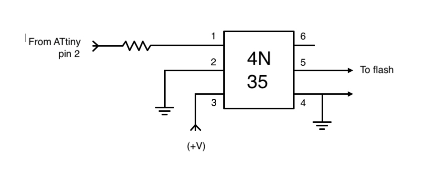
To connect the flash to the circuit, we need an optocoupler or a MOSFET.
The circuit schematic needed for connecting the flash.
int laserPin = 0;         // red wire from laser
int potPin = 2;           // potentiometer to read delay
int optoPin = 3;          // towards the optocoupler
int buttonApin = 1;       // pushbutton
int photocellPin = 4;    // the cell and 10K pulldown are connected to A1
int photocellReading;     // the analog reading from the sensor divider

void setup(){
  // We'll send debugging information via the Serial monitor
    Serial.begin(9600);

    //#define photocellPin 1
    pinMode(laserPin, OUTPUT);
    pinMode(buttonApin, INPUT_PULLUP);
    pinMode(photocellPin, INPUT_PULLUP);
    pinMode(optoPin, OUTPUT);
    pinMode(potPin, INPUT_PULLUP);
    }

void loop() {
  // check if button is pressed, only continue when pressed.
    Serial.println("Waiting for buttonpress...");

if (digitalRead(buttonApin) == HIGH) {  // start program if button is pressed
    //start if(buttonpressed) loop
    Serial.println("Button pressed");

// Read value of potentiometer
    int reading  = analogRead(potPin);
    Serial.println("reading potentiometer");
    Serial.println(reading);
    reading = map(reading, 0, 1023, 1, 500);     // scale it to use it with the drops (delay between 1 and 500)

    delay(50);

  // Activate laser
    digitalWrite(laserPin, HIGH);
    Serial.println("Laser Activated");

delay(1000); // delay before open shutter

Serial.println("Drop object");

  // read the value of the photocellPin
    int photocellReading  = digitalRead(photocellPin); //read value photocell and print it
    Serial.println(photocellReading);

  //Check if laser is broken
while (digitalRead(photocellPin)==HIGH){
  Serial.println("Laser uninterrupted");
    int photocellReading  = digitalRead(photocellPin); //read value photocell
    Serial.println(photocellReading);
    }

    // as long as the laser is not broken, this "while" statement will loop.
    // when the laser is broken, the program will continue.

  // laser off
  // turn laser off to not show up in the picture
  // digitalWrite(laserPin, LOW);


    // Wait the amount indicated by the value of potentiometer
    // give the waves time to rise back to the surface
delay(reading);

  //trigger flash - send signal from pin 8
    digitalWrite(8, HIGH);
    Serial.println("FLASH fired");
    delay(1000);
    digitalWrite(8, LOW);

    //wait for flash light to die down
    delay(200);

    //close camera shutter

    Serial.println("END");
    // END OF (buttonpressed) while loop

  digitalWrite(laserPin, LOW);

}}
If you follow this series of instructions, you will have built two circuits which you can use to capture beautiful high-speed shots.
With the use of ATtiny microcontroller, we can control the timing of our delays while also minimizing the size of our circuits.
Featured image used courtesy of Daniel Kux.