There are a variety of ways to control servo motors. Learn about them to help you pick the best option for your project!
In this article, we’ll take a look at the different ways servo motors can be controlled and various methods to make your life easier when you want to use servos in your project.
Another article introduced you to the basics of servo motors in general and what they are best used for. If you don’t know whether they are the right choice for your project, you should check out What Type Motor is Best for My Project? which compares different popular motor types.
Servo Motor Control Signals
Before we begin, let’s take a look at how servos know where they have to turn.
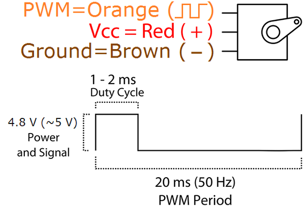
In general, servo motors have three inputs: two power pins and a single data-line. You have to supply a PWM signal on the data line. The duty cycle of that signal will tell the servo how much to turn:
That signal usually has a fixed frequency, and the duration of the high pulse determines the angle. Note that the above image is just an example. Make sure to consider the datasheet of your servo to find the correct frequency and duty cycle for your device.
If the high pulse is one millisecond long, this servo will turn to -90 degrees, and it'll rotate to +90 degrees when the pulse is two milliseconds long. Every value in between gets interpolated to an angle between -90 and +90 degrees.
How to Use a Servo With a Microcontroller
If your project uses a microcontroller, the easiest way to control a servo is to use the MCU itself. There are numerous examples available online, and you can choose from many different libraries that will translate a specific angle to the correct pulse duration.
Using an Astable Vibrator
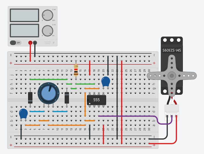
Once you know what the servo expects, it’s easy to build a simple astable vibrator using a 555-timer that can produce the PWM output that’s described above:
Using a servo with a 555 timer to build a simple astable vibrator.
It looks much more complicated than it is. You can find an explanation of this (or a similar) circuit in almost every datasheet of the 555 IC.
This method is suitable for projects that don’t have a microcontroller. Furthermore, it makes it possible to manually control the servo by turning the knob. This circuit is also cheap and doesn’t require any code at all, but it can be tricky to determine the right values for the resistors and capacitors. However, a formula that’ll help you determine the right values is usually also present in most datasheets of this IC.
Using a Dedicated Controller IC
The methods discussed so far are suitable for controlling a small number of servos. However, things can get quite complicated if you want to control many servos simultaneously.
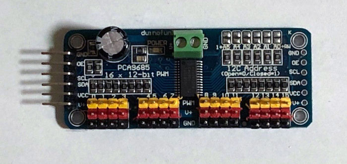
For that reason, many different servo controller boards exist that communicate with a microcontroller and handle direct communication with the servos.
A servo controller board.
It’s important to know that there are many different boards available, and the way they operate can vary greatly. In this particular case, the module can interact with a microcontroller via I2C, and it uses a standard 50Hz RGB driver IC that produces a PWM output that, coincidentally, works well with servo motors.
This method will allow you to control many servos at once without having to use many different outputs of your microcontroller. It, however, requires you to use an MCU in your project.
Determine the Method that Best Fits Your Project
There are many different solutions out there that’ll allow you to control servo motors. If you only have a small number of servos and your project uses a microcontroller anyway, it’s best to use the microcontroller itself to generate the control signal.
But it’s not necessary to utilize a microcontroller because a simple astable circuit can also be used to control a servo motor.
If, however, you want to use a large number of servos in your project, you’re better of using a pre-made servo controller because that will greatly reduce the complexity of your project.


