Keep your projects safe from sudden power surges with this DIY Supercapacitor based UPS!
An uninterruptible power supply (UPS) for 5V boards like Arduino and Raspberry Pi ensures that your projects will be continuously powered by an external power source at the time of minor power fluctuations or power outages.
If you don’t utilize uninterruptible power to a board such as a Raspberry Pi, you risk corrupting its SD card and in projects like data acquisition systems or surveillance, you can’t afford power loss and data corruption.
Supercapacitors can be used as a power bank for a UPS and can be charged and discharged more frequently and more times than a traditional battery. Before making a UPS, we should first understand a supercapacitor’s charging and discharging.
Understanding Supercapacitors
Supercapacitors are like any other capacitor but they can store an extreme amount of energy and have a capacitance in the range of Farads — thousands of times more than more widely-used capacitors.
Supercapacitors are used in many solar-based and battery projects. They charge faster than a battery but as the battery is more energy-dense, capacitors can't store as much energy and discharge quickly. However, supercapacitors do not emit toxic gases like batteries.
How to Charge Supercapacitors
The following considerations must be kept in mind while charging supercapacitors.
- Never apply a positive voltage of more than the supercapacitor rating. For example, if you have two 10V capacitors connected in series, you can’t apply more than 20V to the capacitor combination. Otherwise, you might experience an explosion or at least damage the integrity of the capacitors. Similarly, do not apply negative voltage i.e., never reverse the polarities. The +ve of the supply should be connected to anode and –ve terminal to GND.
- Supercapacitors charge very quickly because of their low internal resistance or ESR (equivalent series resistor). Due to this property, they take as much current as they can from the power supply.
- As there is a large current flowing to capacitors, they look like a short circuit for the supply.
- When you power batteries with their equivalent voltage supply (for example, when a 12V battery is powered by a 12V supply), you can’t leave them unattended or you might damage the battery’s integrity and this damage may be permanent. This is not the case in capacitors. You can apply the equivalent voltage across it and leave them unattended indefinitely.
Discharging Supercapacitors
Supercapacitors discharge very rapidly, so there will be a large current flowing at the discharging end. When we apply this power to a board or IC, we must power them via a boost converter or a buck converter which consists of all safety features like high discharge shutdown, thermal cut-off, and under-voltage shutdown.
If you short circuit a supercapacitor, a large current flows through it. For example, with a capacitor of 10V voltage rating and an assumed wire resistance of 0.1 ohms, the current flowing across the wire would be 10V /0.1 = 100A. You might not want to touch those leads when this happens.
Supercapacitors are designed to discharge very rapidly, but if you short circuit a battery, you will face an explosion or leakage.
Calculating How Long a Supercapacitor Can Last in a Project
If we are using a supercapacitor as a backup power source, we must also calculate how long a supercapacitor can power projects in the event of a power outage.
In this project, we have a supercapacitor combination of 5.4V, 250F made by connecting two 2.7V, 500F capacitors in series. The minimum voltage that can be boosted by a boost converter is chosen as 3V (below which there is not much juice left in the capacitors).
A typical Raspberry Pi project with a 64GB SD card consumes around 1A of current. This is equivalent to 5.4 ohms of resistance across the capacitor. Thus, in this case, the backup time will be around 10 minutes. The formula used is:
Where:
- E = 3V
- V = 5.4V
- R = Load resistance (5.4 ohms)
- C = 250F
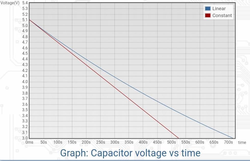
Capacitor discharging waveform
However, this is just an approximate time. We are powering our board with a boost converter, so there will be some extra power loss. Also, the efficiency depends on the ESR of capacitors. Here, the capacitors are connected in series, so their internal resistance will add up and create some loss.
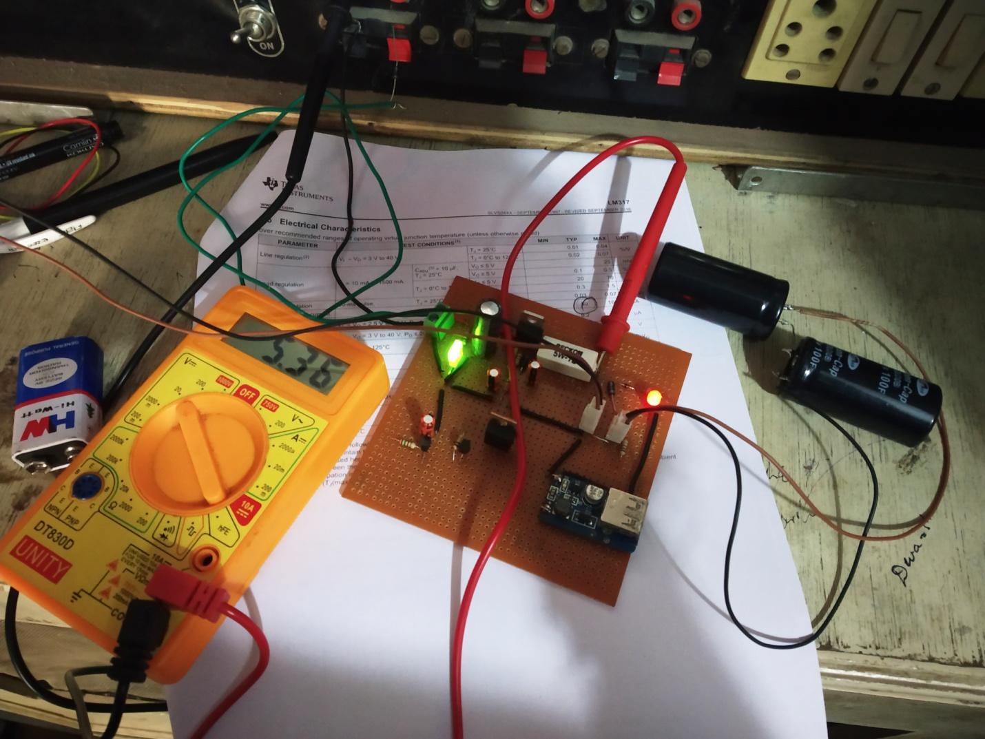
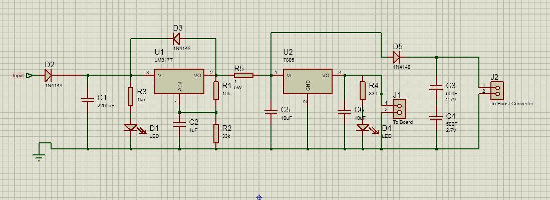
The Supercapacitor Power Supply Circuit
The circuit is built around a linear voltage regulator IC LM317 which can supply a constant current and voltage to the capacitors. With the help of 33k and 10k resistors, we adjust the output voltage to 5.4V.
You can choose the resistor combination arbitrarily, but a high value of resistance is recommended because these resistors will sink the current to ground causing power loss. A 1 ohm, 5W resistor is used to limit the current to 1A.
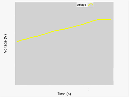
The output of the regulator goes to the board and supercapacitors. The node voltage at the output of the regulator will exponentially rise with the charging of the capacitors, so an indication is needed to let us know that the node voltage is greater than 5V and it can then power the boards. A 7805 5V voltage regulator IC is added so that we can apply a stable 5V to the boards.
Node voltage at the output of regulator which rises exponentially from low voltage
The output of the supercapacitors is applied to the boost converter which will supply power to our board in the event of a power outage.