Learn all about an LED driver and why you should use Constant Current Supply for LEDs in this tutorial!
An LED driver is an electronic circuit used to power an LED (light-emitting diode). LED drivers are widely used for driving high voltage LEDs or lamps or miniature LEDs for indication via microcontroller signals. An LED driver circuit must provide enough current to light up the LED but must limit the current to prevent damage.
A constant current regulator is commonly used for high power LEDs. It provides a constant current which will light up the LED and not damage it. A constant current supply provides a constant current independent of the load resistance, so the supplies don't apply current to load according to Ohm's law but are still constant for all loads. Achieving the correct current regulation of these constant current supplies can be complex, which is what this article covers.
Why Use Constant Current Supply for LEDs?
An LED is a PN junction diode with a forward voltage drop that remains constant over a wide current range. When the forward voltage applied to an LED is less than the forward voltage drop, no current flows through the LED and it will not light up (or it lights up dimly) with a lower current flowing through it. If the forward voltage applied is higher than a certain limit, the current exceeds its maximum rating and the LED overheats. Due to overheating, the forward voltage drop decreases and the current increases more.
In a nutshell, we can say that a small increase in applied forward voltage can greatly increase the current through the LED. So, a constant current supply is needed and an LED should only be powered from a constant current supply.
Designing LED Driver Circuits
A very basic LED driver circuit is a series resistor. A current limiting series resistor is used as an LED driver for most miniature low powered LEDs. To calculate the series resistance, we need to use Ohm’s law. The resistance value can be calculated by:
LED manufacturers also provide LEDs with an inbuilt series resistor but this makes it so you can't adjust its brightness. However for purposes when you don't want to populate your PCBs or adjust the brightness, you can use these LEDs.
This method of driving an LED is highly inefficient as the extra power is dissipated in the form of heat by the series resistor. For a more efficient circuit, we can use transistors to create a constant current supply.
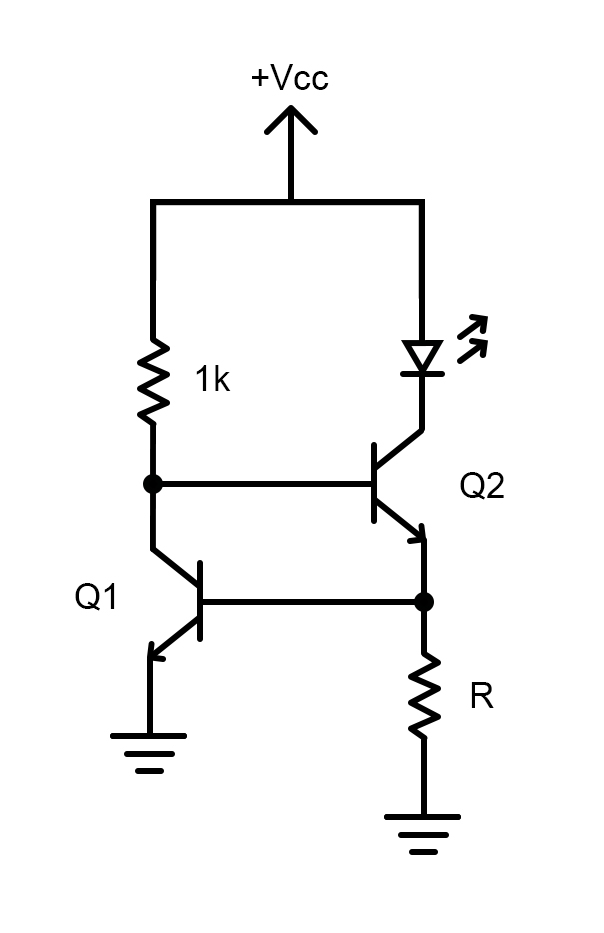
The circuit presented here is a very popular LED driver circuit which can also be used for LED combinations.
Constant current LED driver circuit
Here, when the voltage exceeds the forward voltage of the LED, the collector voltage increases in Q2 as does the base voltage of Q1. This saturates Q1, avoiding a further increase in current to the LED. The unknown resistance R here can be calculated by the following equation:
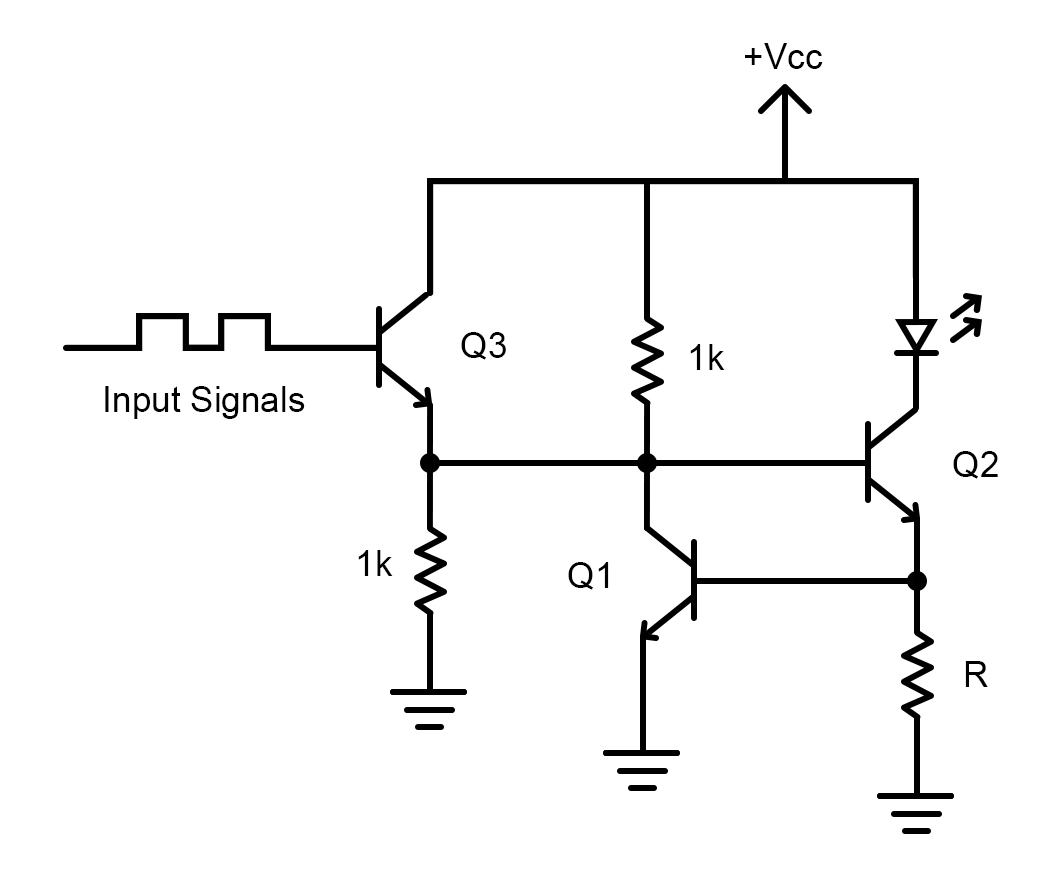
When you want to drive an LED with a microcontroller signal or similar low voltage signals, we can add an emitter follower circuit and apply the output to the base of Q1. An emitter follower circuit is very similar to a buffer circuit but it is made of a transistor and the output lags by 0.7V due to base-emitter voltage drop.
Logic input based LED driver circuit
For a parallel combination of LEDs, please take into account that there will be some manufacturing variations in LEDs. Let's say you have a current limiting resistor that limits the current to 40mA and you are powering a parallel combination of two LEDs. What happens is the first LED draws 20mA at 3V and another one might draw 20mA at 2.9V or 3.1V, so the LED drawing slightly more current begins to heat.
Due to heating, the first LED’s internal resistance decreases and will try to hog all the current which could ruin it. Then, the current will flow through the remaining LED, ruining that one as well. If you have more LEDs, similar things happen and it may lead to a catastrophic failure unless every LED is thermally calibrated. But even then, it's not advisable to put LEDs in parallel but instead in a series combination.
LED Arrays
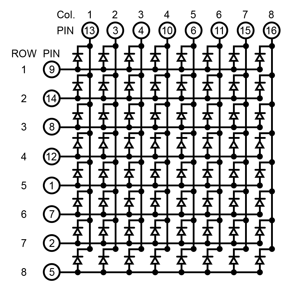
The LED array is a display solution in which each pixel is an LED. Below is the setup for a simple LED array made from 64 LEDs. It's not practical to power each LED individually (especially for 64 LEDs!) and so an LED array is created which to bring down the control pins to 16 consisting of 8 rows and 8 columns.
The 16 control pins can be controlled by a shift register. Each shift register can control eight bits, so we can daisy chain two shift registers to control the complete array. When we provide serial data to each shift register, they can drive eight bits and as we apply the same clock signals, we synchronize the outputs.
When you want to create fancy displays with LED arrays, you can connect the LED array to a 32-bit microcontroller or a board like Arduino UNO and then connect the rows and columns to individual digital output pins. It's an easy process, but when you want to control each LED independently —i.e., turn it ON-OFF and vary its brightness — then you need some dedicated LED array drivers for this.
For these applications, you need a controller that provides individual PWM controlled outputs for each output pin. Then we can use a PWM decoder to convert the PWM signals to the analog output and adjust the brightness of each LED. There are LED array drivers available in the market with various channels available to meet your project’s demands.
A Review of LED Drivers
To summarize what we have discussed in this article, we have discussed about LED drivers, why LEDs should only be powered by a constant current supply, some constant current supplies for LEDs, and how to drive an LED array.