In this article, learn about an essential law in circuit design—Ohm's law—and see how it works in common examples.
Ohm’s law is arguably one of the most important laws in electronics and centers on the relationship between voltage, current, and resistance. It is often used in even the most trivial circuits and a good understanding of it can help you go a long way.
What is Ohm's Law?
Simply put, Ohm's law states that the current through a component (such as a diode or resistor) is equal to the voltage across that component divided by that component’s resistance.
To sum that up in an equation, we get:
where V=potential difference, I=current, and R=resistance.
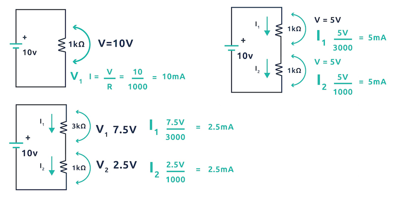
The voltage across a component such as a resistor or LED may not be the same as the voltage of the power supply. Assuming that you are already familiar with voltages in series and potential divider circuits, the first simple examples below show the voltages across resistors when in different configurations.
Voltages across resistors in different configurations.
In the examples above, if we wanted to calculate the current through a resistor, we would use the voltage across it instead of the 10V from the battery.
In the first example, the resistor is in parallel with the battery and therefore has 10V across it.
In the second example, the two resistors (which are both 1kΩ), have the same voltage across them (potential difference).
In the third example, the 3kΩ resistor has 7.5V across it whereas the 1kΩ resistor has 2.5V across it.
We can see from these examples that if we add all the potential differences together we get the same voltage that is supplied by the voltage.
Applying Ohm's Law to Calculate Current Flow
To see how Ohm’s law works, let’s apply it to each example to see the current flowing in the resistors!
When resistors are in parallel current can split up depending on the sizes of the resistances as shown in the example below.
An example of calculated current flowing in the resistors.
A Quick Review of Ohm's Law
- Components in parallel ALWAYS have the same voltage across them all.
- Components in series ALL have the same current flowing through them.
- Current splits when it goes into components in parallel.
- Current combine when they meet up into a single wire.
- Voltages around a circuit always add up to the voltage supplied by the power source.
Utilizing Ohm's Law as a Maker
So far the examples considered are great for homework assignments but not very helpful for makers when designing circuits. Therefore, what examples can makers expect to run into and how does Ohm’s law apply to these situations?
Example 1: LEDs
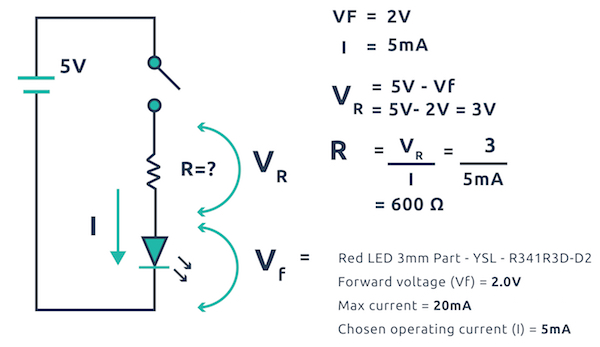
LEDs are a very common example whereby a microcontroller or other circuit may be controlling an LED. Since LEDs are semiconductors, they have a very low resistance. When conducting, they require a series resistor otherwise they may overheat and break. The value of this resistor can be calculated using Ohm's law and is a very easy calculation.
- Determine the voltage size that will turn the LED on and off (5V, 3.3V for example)
- Determine the forward voltage of the LED (this can be found in the datasheet). Note: Red LEDs typically have a forward voltage of 1.8V and white LEDs typically have a forward voltage of 3V.
- Determine the voltage that will remain after the forward drop (input voltage minus forward voltage)
- Decide what current the LED will consume (check the datasheet for maximum ratings)
- Calculate the needed series resistor using V = IR
Using Ohm's Law to calculate the needed series resistor for a project using an LED.
Example 2: Microcontroller Outputs
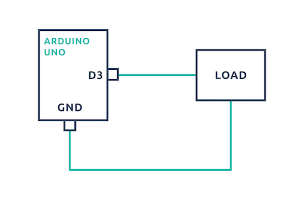
Some designers may wish to connect devices directly to the outputs on a microcontroller. In order to do this, it is imperative to check that the device does not draw more current than the microcontroller output can handle.
If the device does draw more current than the microcontroller can handle, then the circuit runs the risk of damaging the microcontroller. To determine this will happen, the current draw needs to be calculated and then compared to the max current output of the microcontroller pin.
The max current output can be found on the datasheet of the microcontroller, but keep in mind that some pins may be able to source more current than others. The output voltage of the microcontroller will also be needed as well as the resistance of the output load.
- Determine the resistance of the output device.
- Determine the voltage output of the microcontroller.
- Determine the max current output of the microcontroller pin.
- Calculate the drawn current.
- Compare the drawn current with the max output.
A sample circuit diagram of a connection between a microcontroller (in this case, an Arduino UNO) and a device.
Additional Resources
Knowing how to utilize Ohm's law to calculate current, voltage, and resistance by hand is worth learning. If, however, you're pressed for time or want to double check your calculations, there is an online Ohm's Law calculator to help!