Get started with the basic tools of the Autodesk EAGLE and learn how to draw a simple schematic.
There is a reason EAGLE, first as Cadsoft EAGLE and now as Autodesk EAGLE, continues to be used at every level of education, from the beginner DIY enthusiast to the professional designer that implements EAGLE into complex demanding projects. It is affordable, easy to use, and is already used in the market, making it the go-to program for most projects.
In this tutorial, I’ll cover how to get started and the basic tools used to draw a simple schematic. I hope you will find this tutorial useful.
Getting Started
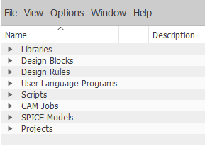
First-time users of EAGLE will be greeted with the rather confusing Eagle Control Panel. You probably expected to see a direct-to-schematic approach, but no, this isn’t a very beginner-friendly application (but it’s very rewarding indeed, so stay tuned).
I’ve found the newest version (9.4) is easier to use as a starter than some of the older versions.
Start by going to File>New>Project. A new project should appear. You can give it a name, but I chose not to.
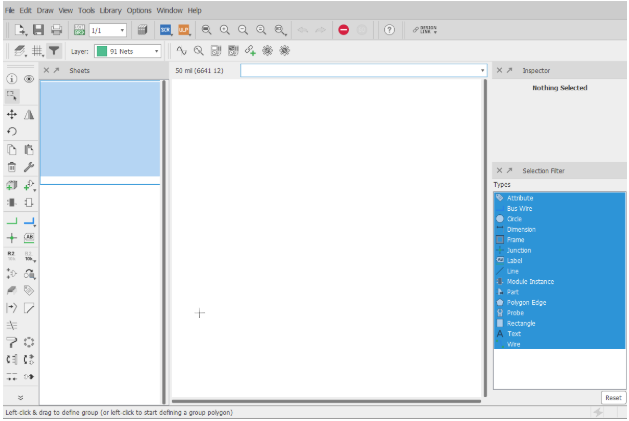
Now go to File>New>Schematic. This will create a new schematic in the project that was currently opened.
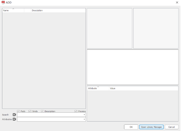
You will be greeted with another less-than-intuitive window where there is seemingly no way to start drawing a schematic. You may have clicked the Add Part tool, only to be greeted by a window that shows no components to be added, and probably tried another way, as I did when I first started learning.
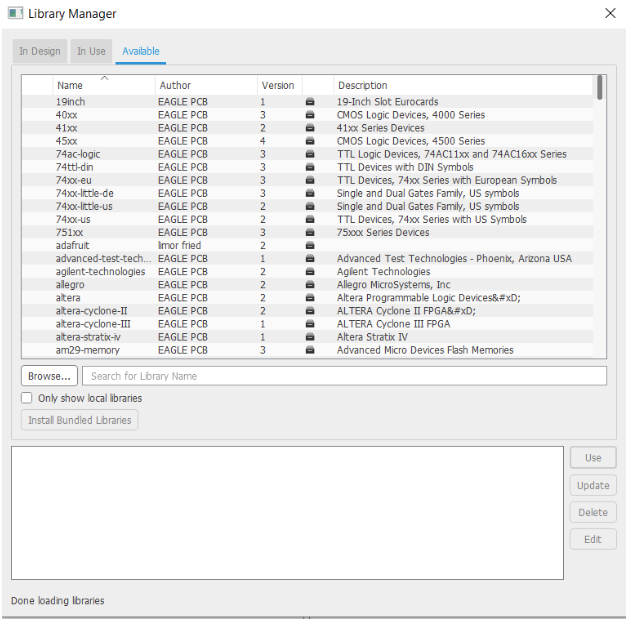
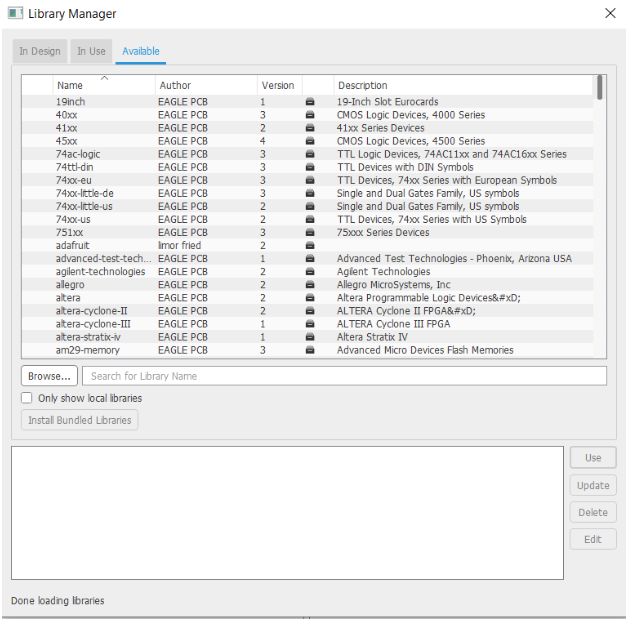
In earlier versions, this was more complicated but now you only need to click the Open Library Manager button and go to the Available tab.
You may choose to download all the available libraries, but if you aren’t keen on waiting for 412 (as of May 2019) libraries to download, I recommend searching for the libraries by SparkFun as well as the libraries rcl, linear, transistor-fet, transistor-npn, transistor-pnp, and transistor-power, all in lbr format.
The libraries by SparkFun are easily the most useful libraries for fiddling with Arduinos, Raspberry Pi, smart home systems, and most hobby electronics involving microcontrollers.
Drawing in EAGLE
We’re finally ready to start drawing! Let’s draw a simple environment for an ATMega328P, the brain of the Arduino UNO.
I usually start drawing a schematic by adding the needed components first.
Note: Be aware of not just the component name and symbol, but it’s chosen PCB layout as well! For example, you may have chosen a 16MHz passive crystal correctly, but you chose its layout as SMD when you really needed a through-hole crystal. Also, pay attention to pin spacing. This won’t matter much now but will matter when we transfer the schematic design to a BRD file.
Drawing the DIYduino Schematic
We’ll start by drawing the DIYduino schematic, the simple, bare-bones ATMega328P environment.
For this, add the following parts to the schematic sheet:
- 1x ATMEGA328P_PDIP
- 1x CRYSTAL-16MHZPTH-HC49US
- 1x LED5MM
- 1x RESISTORAXIAL-0.3
- 1x 1KOHM-HORIZ-1/4W-1% (1KOHM)
- 1x 0.1UF-KIT-EZ-50V-20%
- 2x 22PF-PTH-2.54MM-200V-5%
- 1x 5V
- 5x GND
We start by connecting the power rails.
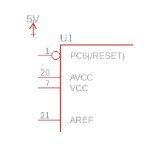
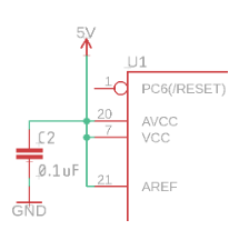
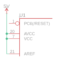
Place the 5V supply symbol above the power pins (VCC).
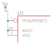
Find the small circles appearing around pins when you approach them with the cursor, click on VCC, and then click on the 5V symbol.
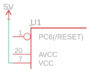
Notice how the net, wire, line, whatever you want to call it, went the exact opposite way of what we desired and connected? We need to delete this. Choose the DELETE tool and then click on all the nets in order to delete them.
You can change the direction in which turns are made by right-clicking your mouse. Choose the NET tool again, and right-click. You will see the nets turn the other way.
Congrats! The first connection was made.
If drawing schematics was equivalent to driving a car, this is the equivalent of turning right and left. It’s essential, and very intuitive once you learn it.
The AVCC is the supply pin of the internal Analog-to-Digital Converter, and AREF is its internal analog reference voltage input, we pull nets from all of them to the supply net.
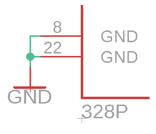
Now connect the ground to both ground pins and place the 100nF capacitor between ground and VCC? Can’t find one? It’s the 0.1uF we added earlier, of course!
Tips to Keep in Mind
PRO TIP #1: If you add another component to an existing net, try to connect to an already existing junction to make your schematics clutter-free. They are easier to read this way and look neat.
PRO TIP #2: Place individual GND symbols wherever you can. The GND symbols change the name of whichever net it’s connected to GND, so the program considers all the components connected to GND symbols a part of a single large net. This too reduces clutter and makes things look neat and professional.
Additional EAGLE Projects
