Learn how the serial peripheral interface (SPI) communications protocol works and tips for its implementation in design.
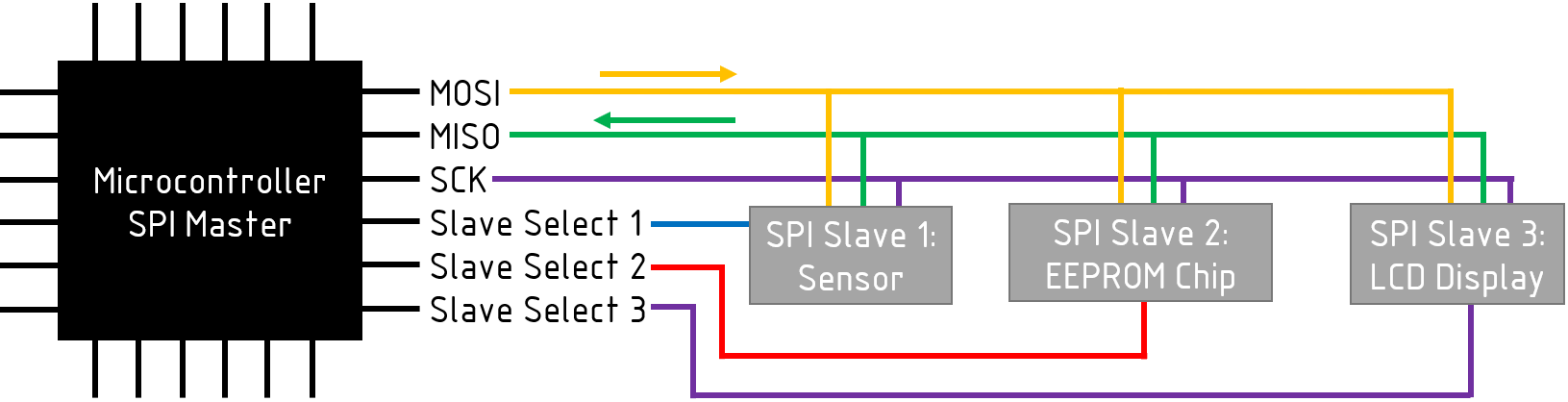
Serial peripheral interface (SPI) is a serial communication protocol originally developed by Phillips Semiconductor to allow a system of devices to talk to each other. Out of popular communications protocols like UART and I2C, SPI (typically pronounced S-P-I) is the most straightforward serial communication protocol that works by using four wires:
- MOSI: Master Output, Slave Input
- MISO: Master Input, Slave Output
- SCK: Clock line to time the transfer of data
- Slave Select: Chooses which device to communicate to
You can see how these four wires work together in Figure 1.
Aside from microcontrollers, other typical devices that use SPI include EEPROM, sensors, wireless modules, shift registers, LCD displays, etc. When it comes to choosing a device, SPI is a good choice when speed is the most important factor.
How Does SPI Work?
SPI is arranged in a master-slave orientation where the master device initiates the communication, determines the clock speed, and picks the devices to talk to while the other slave devices wait for the master device to communicate with them. Typically, the microcontroller you are programming will be the SPI master.
The master initiates communication with a slave device by dropping the slave select pin for the corresponding slave device to 0V.
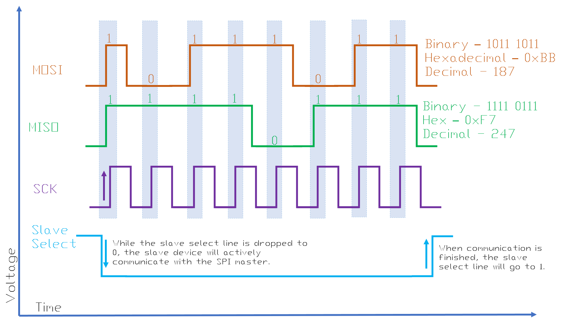
The master device controls the clock signal by creating a pulse from logic 0 (0 Volts) to logic 1 (3.3/5 Volts) to control the speed and to time the data passing through the MISO and MOSI lines. Think of the clock as a metronome while the serial data can be like notes.
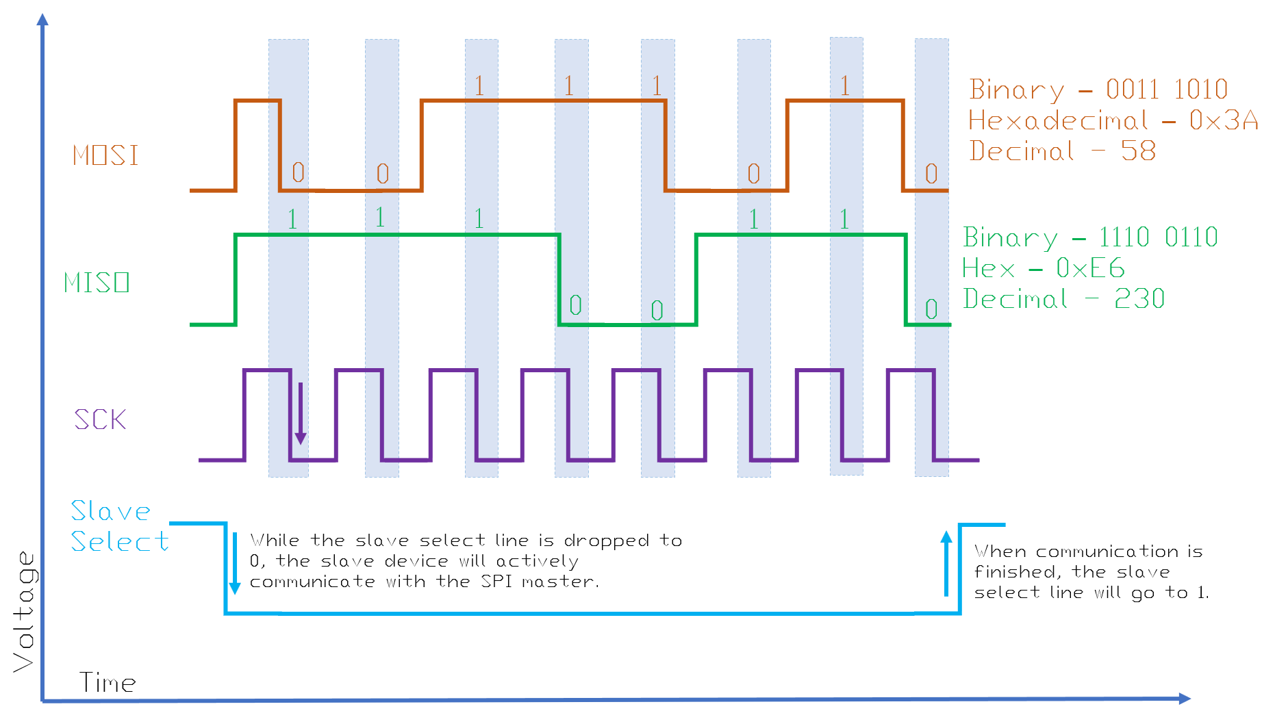
Now moving on to how we read the bits going through the MISO and MOSI lines, we first have to determine the polarity of the communication. The SPI polarity basically determines whether data will be read when the voltage of the clock line rises or when it falls. See Figures 2 and 3 to see the difference between how the data is read depending on the polarity.
Figure 2. SPI timing diagram when the data is read on a rising clock edge.
Figure 3. SPI timing diagram when data is dead on a falling clock edge.
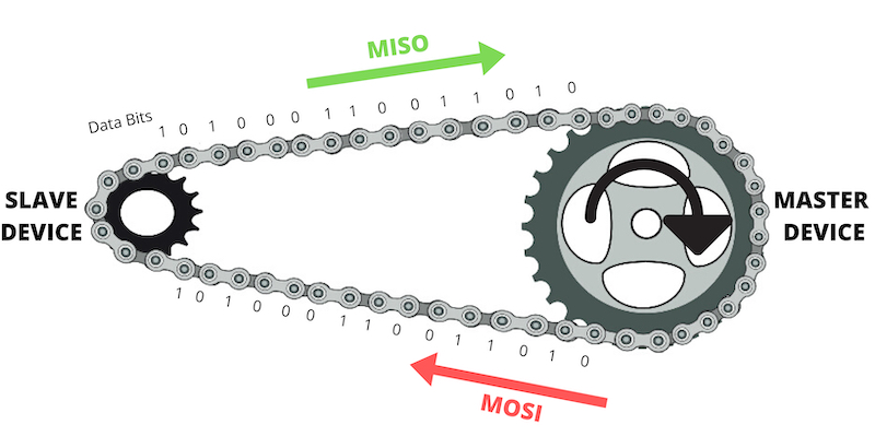
Visualizing SPI as a Mountain Bike Gear Train
SPI data travels in a way where both the read and write lines work simultaneously. Visualize SPI as a gear train in a mountain bike:
- Think of the gear at the pedals as the SPI master.
- The multiple gears on the rear wheel of the bike as the slave devices.
- The RPM of the pedaling motion can be the clock speed.
- The chain as the data lines. Assuming that the bicycle is pedaling forward, the topside of the chain moving towards the main gear (master) will be the MISO line and the lower side of the chain moving away from the main gear will be the MOSI line.
- The gearshift as the slave select.
Visualize the parts of SPI as a gear train in a mountain bike.
Whether you are reading or writing to a device, the master device is always writing to the slave device even if when the master is reading data from the slave device to “push” the read data out. Like a bicycle chain, each of the links in the chain push each other so the whole chain can move. With that said, during a read sequence, you can use an arbitrary number to write. Usually, 0 is used:
Ex: SPI_Read_Value = SPI_Write(0x00);
After the communication is finished, the final piece is to set the slave select back to logic 1.
What to Keep in Mind When Writing Your Code
There are many different types of SPI devices you can choose from so it’s important to read the datasheet if a library is not available for the microcontroller you’re programming.
- Check the voltage level of your device. If you are using a 5V Arduino, make sure the SPI slave device is also a 5V device. If it’s a lower voltage device like 3.3V, make sure to put a logic level shifter so the lower voltage slave device does not get damaged.
- Double-check to make sure you have the clock polarity of the master device match the slave device.
- In the device datasheet, look through all the available commands and make sure to make a list of those constant variables in your code.
Thank you for reading! Please feel free to ask questions and request clarifications in the comments.
Additional Resources
- Make: AVR Programming by Elliot Williams: This book clearly explains how to write code for SPI on the AVR toolchain.
- SPI Reference by Arduino.