Introduction to Solar Inverter:
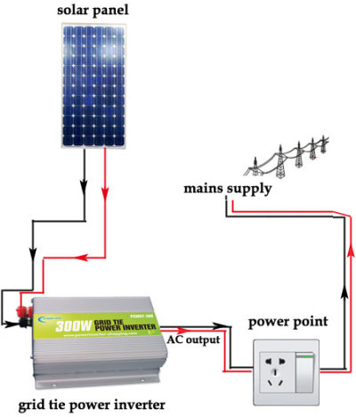
We see many people using Solar inverters these days which proves that its necessity has been increased in the current years. A Solar inverter is similar to a normal electric inverter but uses the energy of the Sun i.e. Solar energy.
A solar inverter helps in converting the direct current into alternate current with the help of solar power. Direct power is that power which runs in one direction inside the circuit and helps in supplying current when there is no electricity. Direct currents are used for small appliance like mobile e phones, MP3 players, IPod etc. where there is power stored in the form of battery. In case of alternative current it is the power that runs back and forth inside the circuit. The alternate power is generally used for house hold appliances. A solar inverter helps devices that run on DC power to run in AC power so that the user makes use of the AC power. If you are thinking why to use solar inverter instead of the normal electric one then it is because the solar one makes use of the solar energy which is available in abundant from the Sun and is clean and pollution free.
Solar Inverter Design:
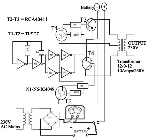
To easily understand the construction of a solar inverter lets discuss the following construction sample:-
According to the circuit diagram initially do the assembling of the oscillator part which consist of the small components & IC. It is finely completed by interrelating the part leads itself and fusing the joints.
Now place the power transistors into the acutely pierced aluminum heat sinks. This is crafted by cutting aluminum sheet into specified sizes and bending their sides, so that it can be hold tightly.
Make use of mica isolation kit to fix transistors in the aluminum heat sink, evade short circuiting & direct contact of the transistors from ground & each other.
Fasten the heat sink congregation to the bottom of a properly ventilated, strong, thick gauge metal enclosed space.
Also fasten the power transformer next to the aluminum heat sinks by making use of screw & bolts.
Now join the suitable points of the assembled circuit board & power transistors on the aluminum heat sinks.
At last connect the power transistor’s productions to the subsequent winding of the power transformer.
End the assembly by fastening and interlocking the outer electrical fittings such as switches, mains cord, fuses, sockets, and the battery inputs.
A voluntary solar power supply circuit and a transformer may be added within to charge the battery when necessary (check diagram).
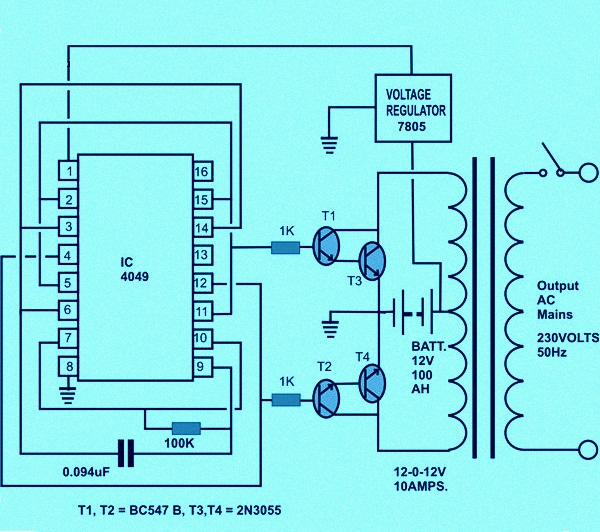
Solar Inverter Circuit Diagram:
Inverter Circuit Schematic
To understand well how to construct a solar inverter, it is vital to study how the circuit operates through with the help of following steps:
N1 & N2 gates of IC 4049 are employed as an oscillator. It carries out the key role of providing square waves to the inverter division.
N3 to N6 gates are employed as buffers so that the circuit is not dependent on load.
Continuously changing voltage from the buffer phase is useful to the bottom of the current amplifier transistors T1 & T2. These transistors perform in harmony with the practical changing voltage and boost it to the bottom of the output transistors T3 & T4.
These producing power transistors swing at a full oscillation, providing the total battery voltage.
This energy produced is from solar panel & is employed to power the output load.