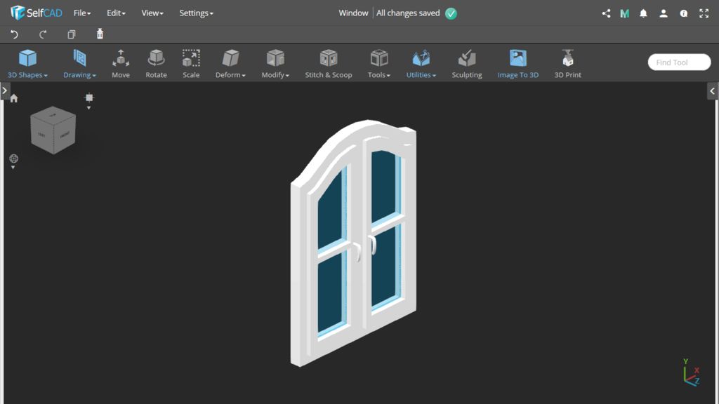
With this tutorial, we will model a nice rounded window in SelfCAD - an online 3D modeling application
Welcome to the next SelfCAD instructable. With this tutorial, we will model a nice rounded window in SelfCAD - an online 3D modeling application.
Welcome to the next SelfCAD instructable. With this tutorial, we will model a nice rounded window in SelfCAD - an online 3D modeling application.
Step 1: Create New SelfCAD Project
Turn on orthographic projection mode.
Launch SelfCAD editor and create a new 3D project.
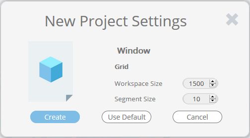
Now you should see the new project settings. Notice that SelfCAD's 1 unit is equal to 1 millimeter. I set Workplace Size to 1500 because it should be enough for my project. Segment Size means the spacing between grid lines. I entered here value 10.
If you want you can change the preferences of your project. I prefer to work in the dark editor mode.
Turn on orthographic projection mode.
Step 2: Add a Cube to the Scene
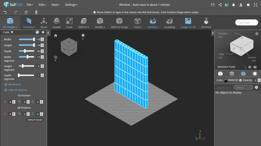
Add a cube. Set its Width to 1000, Height 1400, and Depth 80. We need 6 height segments, 1 depth segment, and 5 width segments, but here we should set the bigger value to get a nicely rounded edge. I decided to enter 12 width segments.
Add a cube. Set its Width to 1000, Height 1400, and Depth 80. We need 6 height segments, 1 depth segment, and 5 width segments, but here we should set the bigger value to get a nicely rounded edge. I decided to enter 12 width segments.
Step 3: Loop Selection
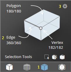
We need to select a loop of edges. Of course you can select them edge by edge, but there is a faster way to do it. First, turn on Mesh+Wireframe mode (1) to see where the edges are. Then choose edge selection mode (2) and open its settings (3). In the selection settings turn on loop selection and click two neighboring edges, like in the second picture. As you can see the whole loop is selected now.
We need to select a loop of edges. Of course you can select them edge by edge, but there is a faster way to do it. First, turn on Mesh+Wireframe mode (1) to see where the edges are. Then choose edge selection mode (2) and open its settings (3). In the selection settings turn on loop selection and click two neighboring edges, like in the second picture. As you can see the whole loop is selected now.
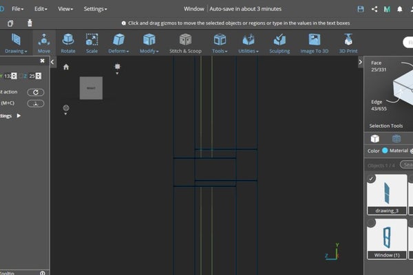
Step 4: Move the Loops
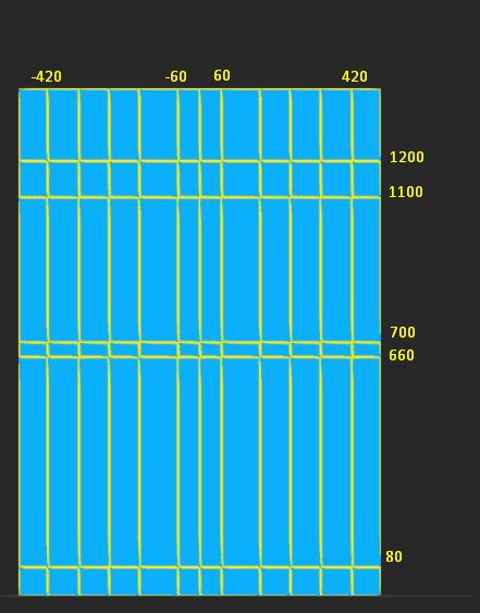
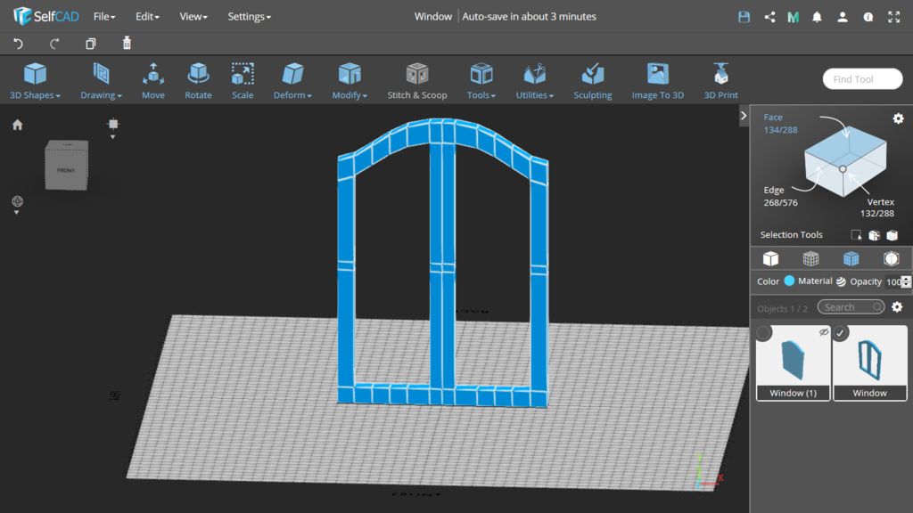
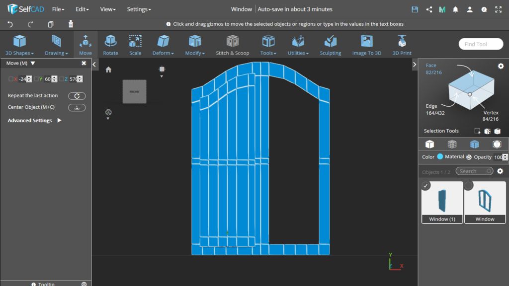
Select the loops and move them using the Move tool. In the image you can see my suggestion of Y and X coordinates of the loops I moved. My idea was to make each part of the window frame 80mm wide. The central, vertical part of the window should be wider.
Select the loops and move them using the Move tool. In the image you can see my suggestion of Y and X coordinates of the loops I moved. My idea was to make each part of the window frame 80mm wide. The central, vertical part of the window should be wider.
Step 5: Use Inflate to Round One Side
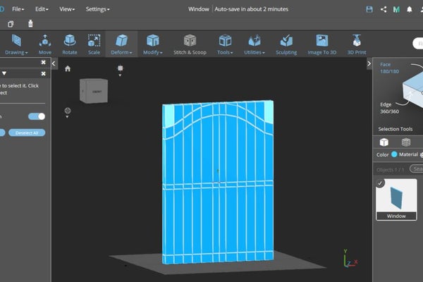
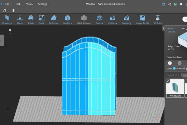
Select two loops as in the first image. Use the Inflate tool (Deform → Inflate or D+I) and set its value to 200.
Select two loops as in the first image. Use the Inflate tool (Deform → Inflate or D+I) and set its value to 200.
Step 6: Extrude Unnecessary Faces
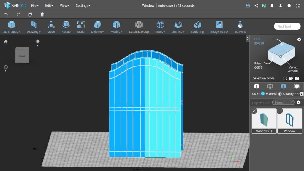
Use Extrusion tool (Modify → Extrusion or M+E) on the selected faces and set the value -80 (because the object is 80mm deep).
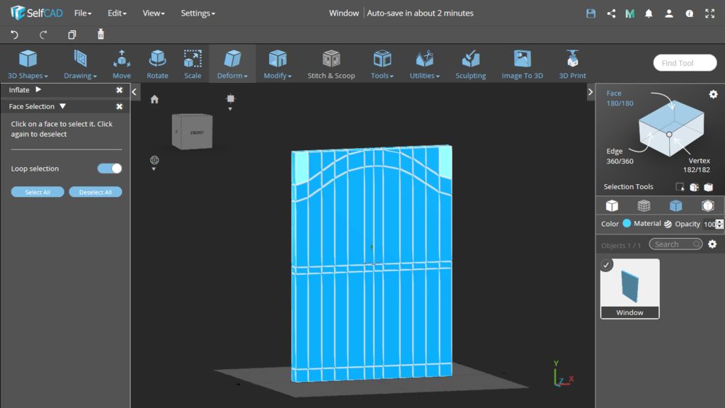
Use Loop Selection in Face Selection mode and click on the faces as in the first image. Notice that only faces on the one side are selected now, not the loop.
Use Extrusion tool (Modify → Extrusion or M+E) on the selected faces and set the value -80 (because the object is 80mm deep).
Step 7: Copy the Object
Select the object and copy it. Press V+H to hide the second object.
Select the object and copy it. Press V+H to hide the second object.
Step 8: Create a Frame
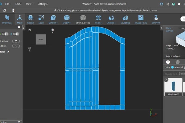
Select the inside faces and use extrude as before to create a window frame.
Select the inside faces and use extrude as before to create a window frame.
Step 9: Model a Window Sash
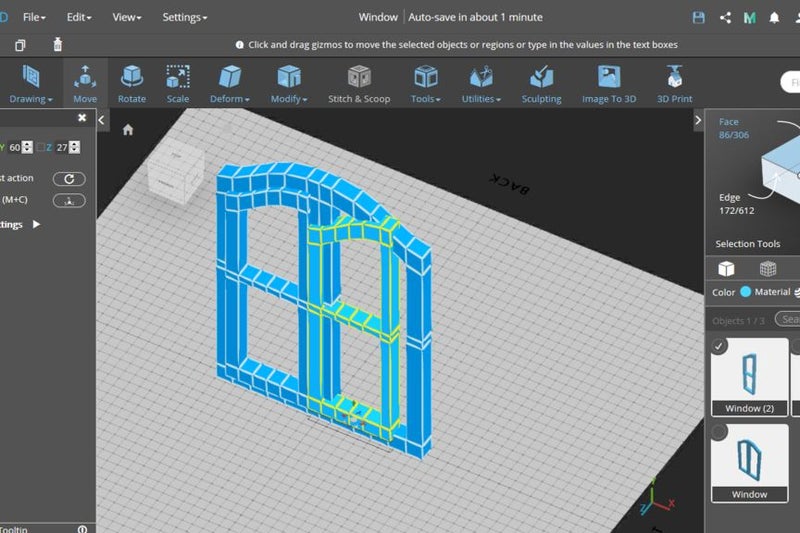
Change the object's scale. The hole should be 360mm wide and 1220mm high, so set the sash Y dimension to 1260 and X dimension to 400mm.
Select the faces on the right side and use Extrude as you did it with the frame.
Change the object's scale. The hole should be 360mm wide and 1220mm high, so set the sash Y dimension to 1260 and X dimension to 400mm.
Step 10: Set the Right Position of the Sash and Cut Holes in It
In order to cut holes for the glazing, use Extrude again.
Use Move to set the right position of the sash.
In order to cut holes for the glazing, use Extrude again.
Step 11: Create the Second Sash and Set Its Position
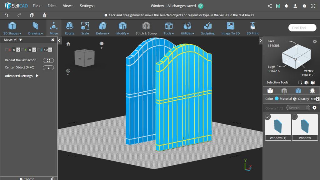
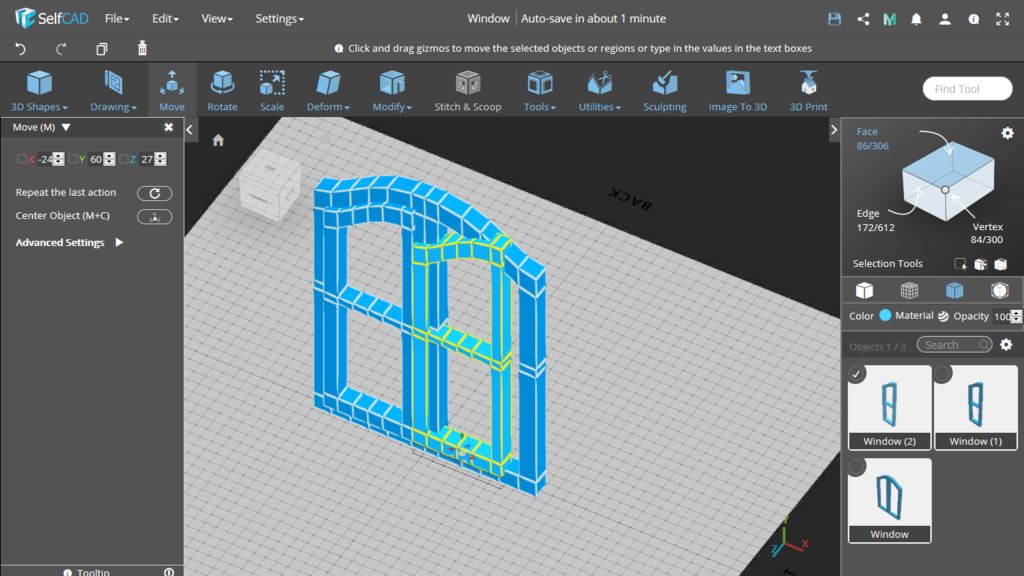
Copy the window sash and use Mirror tool (Utilities → Mirror or U+I) to rotate it (you can use also Rotate in this case). Move the second sash to the right position.
Copy the window sash and use Mirror tool (Utilities → Mirror or U+I) to rotate it (you can use also Rotate in this case). Move the second sash to the right position.
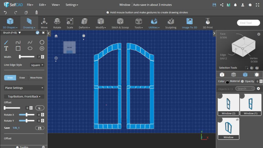
Step 12: Draw Sheets of Glass
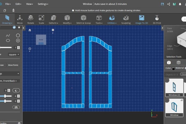
Use the Rectangle and Line tool (Drawing → Free Hand → Rectangle/Line) to draw two sheets of glass. In Plane Settings choose Front/Back plane, in Height Settings leave heights value 20, and in Precision Settings turn on Minimum Step Size and enter there 10 (or less if you need more precision).
Use the Rectangle and Line tool (Drawing → Free Hand → Rectangle/Line) to draw two sheets of glass. In Plane Settings choose Front/Back plane, in Height Settings leave heights value 20, and in Precision Settings turn on Minimum Step Size and enter there 10 (or less if you need more precision).
Step 13: Set the Glass Position
Set the glazing position. Turn on the Wireframe mode to see it better. Use Copy, Mirror and Move tools to create left glass.
Set the glazing position. Turn on the Wireframe mode to see it better. Use Copy, Mirror and Move tools to create left glass.
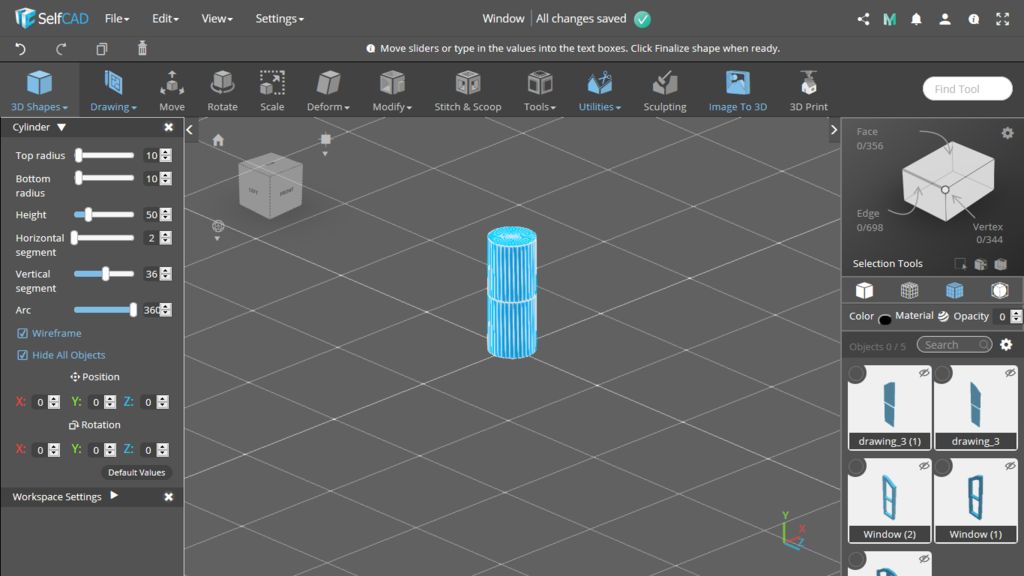
Step 14: Add a Cylinder to the Scene
Add a cylinder. Set its radius to 10, height to 50 and horizontal segments to 2.
Add a cylinder. Set its radius to 10, height to 50 and horizontal segments to 2.
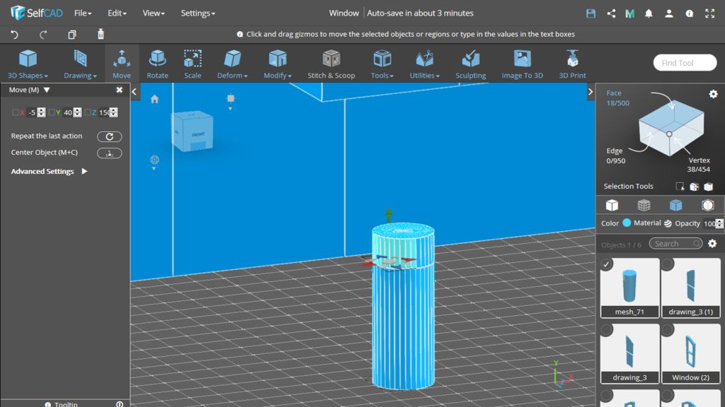
Step 15: Create a Handle
Use Extrude. Set its value to 10 and open advanced settings. Repeat the extrusion 10 times.
Use Loop Selection in Edge Selection Mode to move the middle loop of the cylinder higher.
Select faces only on the one side, as in the image. To do so, you can choose for example Left View and select all visible faces with the right mouse button.
Use Extrude. Set its value to 10 and open advanced settings. Repeat the extrusion 10 times.
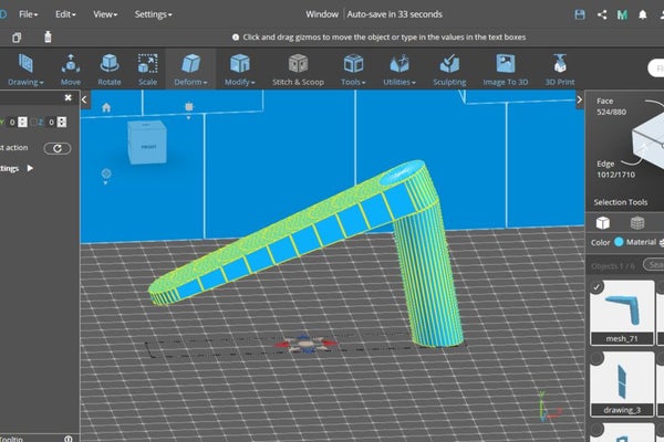
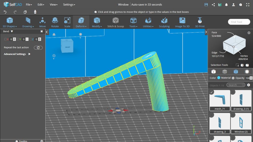
Step 16: Bend the Handle
First, bend the object to the left side, then to the right side.
Turn off the Face Selection tool. Use Bend (Deform → Bend or D+B).
First, bend the object to the left side, then to the right side.
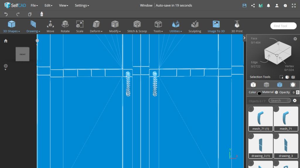
Step 17: Copy the Handle
Copy the handle. Then move both handles to the right position.