This project shows a simple design that can always be modified to add new features.
The GreenPAK™ chips have easy-to-program look-up tables (LUTs) which enable us to easily design a simple yet efficient controller for a line following robot.
The complete design file can be found here. It was created in the GreenPAK Designer software (a part of the Go Configure™ Software Hub).
1. Theory
We will explore both the classic approach using only predefined Logic Gates NAND, AND, OR, NOR, and NOT, as well as taking full advantage of the programmable LUTs the GreenPAK SLG46531 has.
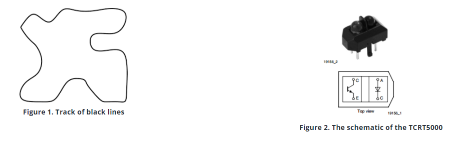
A line follower is a robot that can follow a track of black lines on a white background, as illustrated below in Figure 1.
Black and white has the most contrast properties and allows us to work with the TCRT5000. The detailed schematic of the TCRT5000 is presented just below in Figure 2.
The TCRT5000 is a Reflective optical sensor, which means that it is composed of two parts: an IR LED and an IR receiver. The output is a digital signal HIGH for white and LOW for Black.
Each TCRT5000 has an output that we are going to call IN 1, IN 2, and IN 3.
2. Design
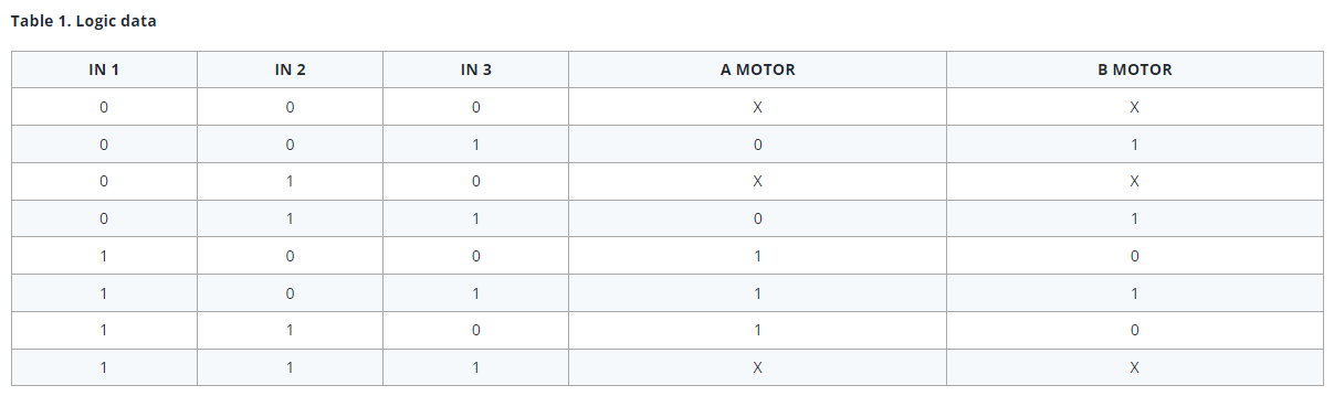
The logic we are going to be implementing is shown in Table 1:
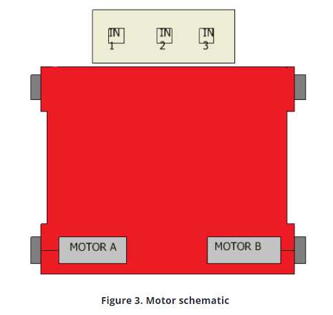
A motor at 1 means that the motor is spinning, and 0 means that it is stopped. In order to keep a simple design, we will only drive two motors. The motors are placed as shown in Figure 3. We could design the sensor array with any quantity of sensors we like, but it can be just three TCRT 5000 arranged as below. An ideal distance between the TCRT 5000s would be the width of the black line it is going to follow.
3. Classic Design Sequence
Following the normal process using the table shown before, we are to simply obtain the logical equations using Karnaugh´s Maps for each motor.
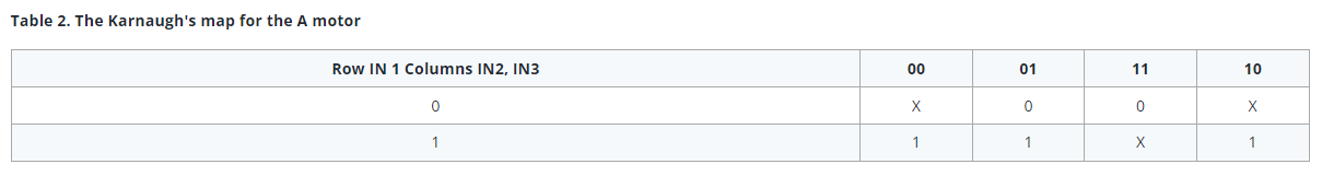
Karnaugh's map for the A motor is represented in Table 2.
X state means that the combination is not expected to appear under normal circumstances, which means that it does not matter if the motor is either spinning or stopped
So the logic equation for the A motor is:
AMotor = IN1
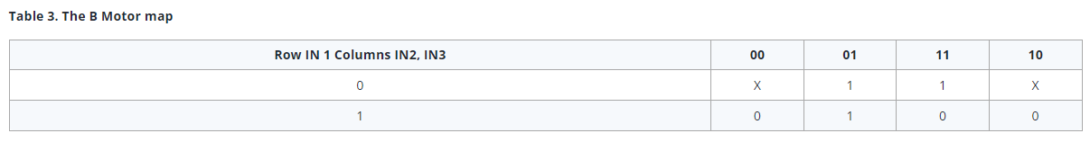
The B Motor map is described in Table 3.
This gives us the logic equation for the B Motor:
BMotor = IN 1´ + IN 2´IN 3
Usually, in order to use only one or two types of logic gates, we do some Boolean algebra until we get the following equivalent equation.
BMotor = (IN 1(IN 2´IN 3)´)´
This line follower is developed using simple logic, which means that going in reverse is not implemented.
In case the three sensors are outside the black line, IN 1, IN 2 and IN 3 will all be reading a HIGH, which for this configuration makes the car spin, until the black line can be found again.
On the other hand, when the three sensors are reading a LOW, the car stops moving altogether.
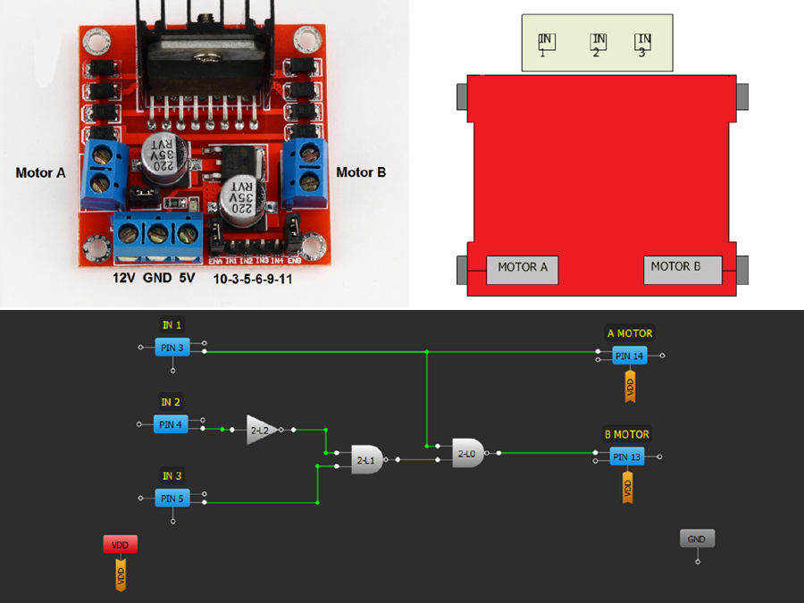
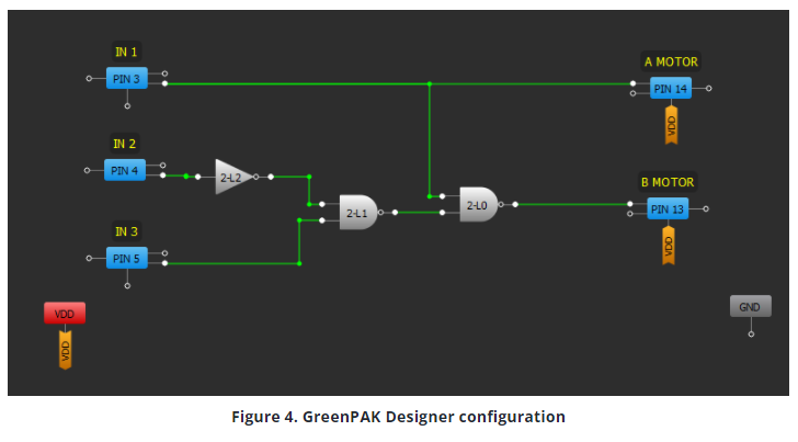
These equations are the logic for the basic line follower, and if we were to program it exactly in the same form, we obtain the configuration shown in Figure 4.
4. Using GreenPAK for Design Optimization
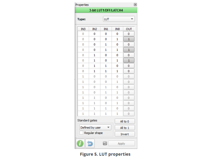
GreenPAK has the advantage that the designs can be implemented using premade logic gates. But what makes it so favored by engineers is their capability to actually implement completely arbitrary Logic tables using their programmable LUTs.
Figure 5 illustrates that using the LUT table is far easier than implementing predetermined logic gates
Using the completely programmable feature of the LUT we can considerably reduce the use of resources inside the GreenPAK, and simplify even further the Line follower design.
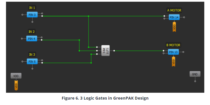
In Figure 6 we can see that just one LUT table can do all the processing done by the other 3 Logic Gates shown in the first GreenPAK Design.
5. Considerations
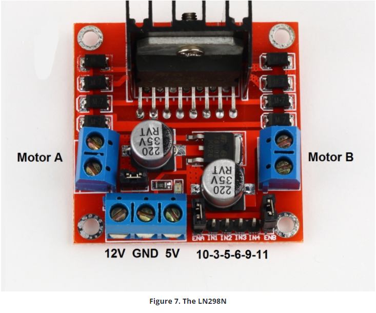
To power up the GreenPAK, we can connect it to the 5v Pin of the LN298N and power the same using a 12-volt battery. This can be seen in Figure 7.
Using this setup, we can add more features to this basic design, implementing PWM to regulate the speed at which the line follower is moving, and enable us to implement a reverse condition if needed.
Conclusion
This project shows a simple design that can always be modified to add new features.
GreenPAKs are a very promising tool for IoT development and as a tool for teaching future electronic engineers. Their low power consumption, small design, and user-friendly developing software make them an interesting and handy technology to become mainstream in study plans for colleges around the world.