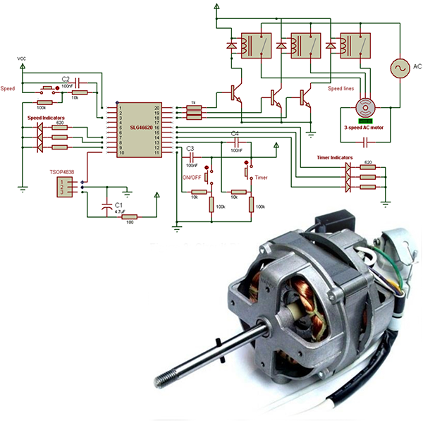
This project details the configuration of a 3-speed single-phase motor control circuit.
Single-phase alternating current motors are typically found in household items such as fans, and their speed can be easily controlled when using a number of discrete windings for set speeds. In this project, we build a digital controller which allows users to control functions such as motor speed and operating time. This project also includes an infrared receiver circuit that supports the NEC protocol, where a motor may be controlled from push buttons or from a signal received by an infrared transmitter.
To carry this out, a GreenPAK™ SLG46620 IC is used as a basic controller in charge of these diverse functions: a multiplex circuit to activate one speed (out of three speeds), 3-period countdown timers, and an infrared decoder to receive an external infrared signal, which extracts and executes a desired command.
If we look at functions of the circuit, we note several discrete functions simultaneously employed: MUXing, timing, and IR decoding. Manufacturers often use many ICs for building the electronic circuit because of the lack of an available unique solution within a single IC. Use of a GreenPAK IC enables the manufacturers to employ a single chip for including many of the desired functions and consequently reduce the system cost and oversight of manufacturing.
The system with all its functions has been tested to ensure proper operation. The final circuit may require special modifications or additional elements tailored to the chosen motor.
To check that the system is operating nominally, test cases for the inputs have been generated with the help of the GreenPAK Designer emulator. The emulation verifies different test cases for the outputs, and the functionality of the IR decoder is confirmed. The final design is also tested with an actual motor for confirmation.
The complete design file created in the GreenPAK Designer can be found here.
1. 3-Speed AC Fan Motor
3-speed AC motors are single-phase motors operated by an alternating current. They’re often used in a wide variety of household machines such as various types of fans (wall fan, table fan, box fan). Compared to a DC motor, controlling speed in an alternating current motor is relatively complicated since the delivered current's frequency must change in order to change the motor speed. Appliances such as fans and refrigeration machines usually do not require fine granularity in speed, but require discrete steps such as low, medium, and high speeds. For these applications, AC fan motors have a number of built-in coils designed for several speeds where changing from one speed to another is accomplished by energizing the desired speed's coil.
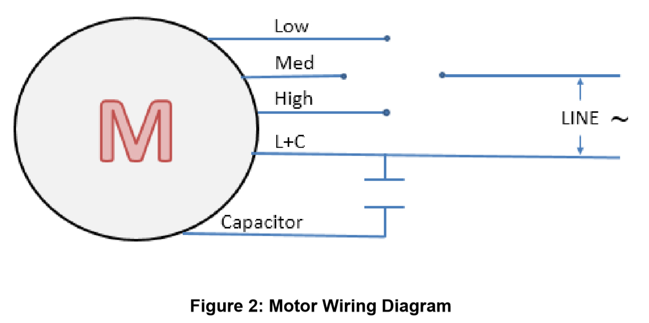
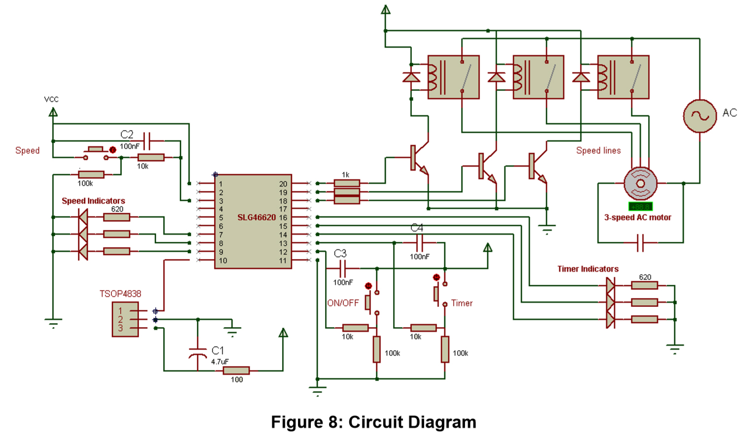
The motor we use in this project is a 3-speed AC motor that has 5 wires: 3 wires for speed control, 2 wires for power, and a start capacitor as illustrated in the Figure 2 below. Some manufacturers use standard color coded wires for function identification. A motor’s datasheet will show the particular motor’s information for wire identification.
2. Project Analysis
In this project, a GreenPAK IC is configured to execute a given command, received from a source such as an IR transmitter or an external button, to indicate one of three commands:
On/Off: the system is turned on or turned off with each interpretation of this command. The state of On/Off will be reversed with each rising edge of the On/Off command.
Timer: the timer is operated for 30, 60, and 120 minutes. At the fourth pulse the timer is turned off, and the timer period reverts to the original timing state.
Speed: Controls the speed of the motor, successively iterating the activated output from the motor’s speed-selection wires (1,2,3).
3. IR Decoder
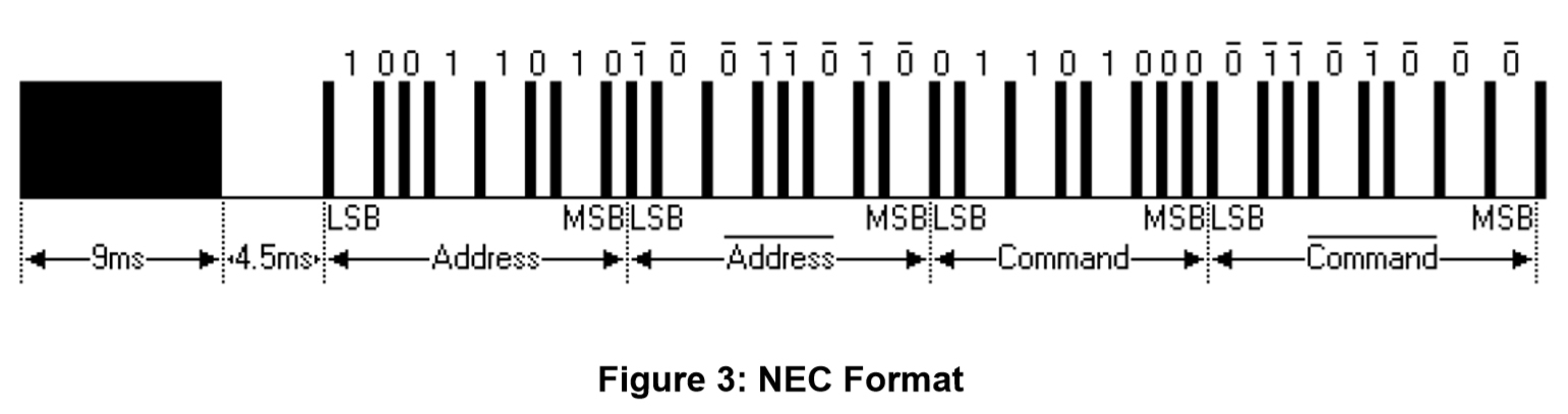
An IR decoder circuit is built to receive signals from an external IR transmitter and to activate the desired command. We adopted the NEC protocol because of its popularity amongst manufacturers. NEC protocol uses "pulse distance" to encode every bit; each pulse takes 562.5 us to be transmitted using the signal of a 38 kHz frequency carrier. The transmission of a logic 1 signal requires 2.25 ms while transmission of a logic 0 signal takes 1.125 ms. Figure 3 illustrates the pulse train transmission according to the NEC protocol. It consists of 9 ms AGC burst, then 4.5ms space, then the 8-bit address, and finally the 8-bit command. Note that the address and the command are transmitted twice; the second time is 1's complement (all the bits are inverted) as parity to ensure that the received message is correct. LSB is transmitted first in the message.
4. GreenPAK Design
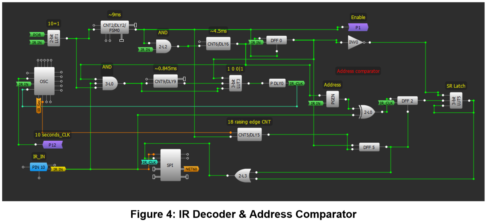
The received message’s relevant bits are extracted over several stages. To begin, the outset of the message is specified from 9ms AGC burst using CNT2 and 2-bit LUT1. If this has been detected, 4.5ms space is then specified through CNT6 and 2L2. If the header is correct the DFF0 output is set High to allow reception of the address. The blocks CNT9, 3L0, 3L3 and P DLY0 are used to extract the clock pulses from the received message. The bit value is taken at the rising edge of IR_CLK signal, 0.845ms from the rising edge from IR_IN.
The interpreted address is then compared to an address stored within the PGEN using 2LUT0. 2LUT0 is an XOR gate, and the PGEN stores the inverted address. Each bit of the PGEN is sequentially compared to the incoming signal, and each comparison's result is stored in DFF2 along with the rising edge of IR-CLK.
In case any error has been detected in the address, the 3-bit LUT5 SR latch output is changed to High with the aim to prevent comparing the rest of the message (the command). If the received address matches the stored address in PGEN, the second half of the message (command & inverted command) is directed to SPI so that the desired command can be read and executed upon. CNT5 and DFF5 are used to specify the end of the address and start of the command where ‘Counter data’ of CNT5 equals 18: 16 pulses for the address in addition to the first two pulses (9ms, 4.5ms).
In the event that the full address, including header, has been correctly received and stored in the IC (in PGEN), the 3L3 OR Gate output gives the signal Low to SPI's nCSB pin to be activated. The SPI consequently begins to receive the command.
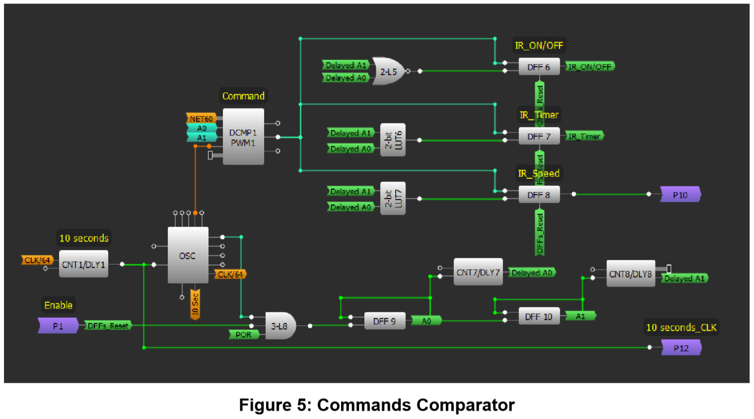
The SLG46620 IC has 4 internal registers of 8-bit length and it is thus possible to store four different commands. DCMP1 is used to compare the received command to the internal registers and a 2-bit binary counter is designed whose A1A0 outputs are connected to MTRX SEL # 0 and # 1 of DCMP1 in order to compare the received command to all the registers successively and continuously.
A decoder with latch was constructed using DFF6, DFF7, DFF8 and 2L5, 2L6, 2L7. The design operates as follows; if A1A0=00 the SPI output is compared to register 3. If both values are equal, DCMP1 gives a High signal at its EQ output. Since A1A0=00, this activates 2L5, and DFF6 consequently outputs a High signal indicating that the signal On/Off has been received. Similarly, for the rest of the control signals, CNT7 and CNT8 are configured as 'Both Edge Delay' to generate a time delay and allow the DCMP1 to change the state of its output before the value of output is held by the DFFs.
The value of the On/Off command is stored in register 3, timer command in register 2, and speed command in register 1.
5. Speed MUX
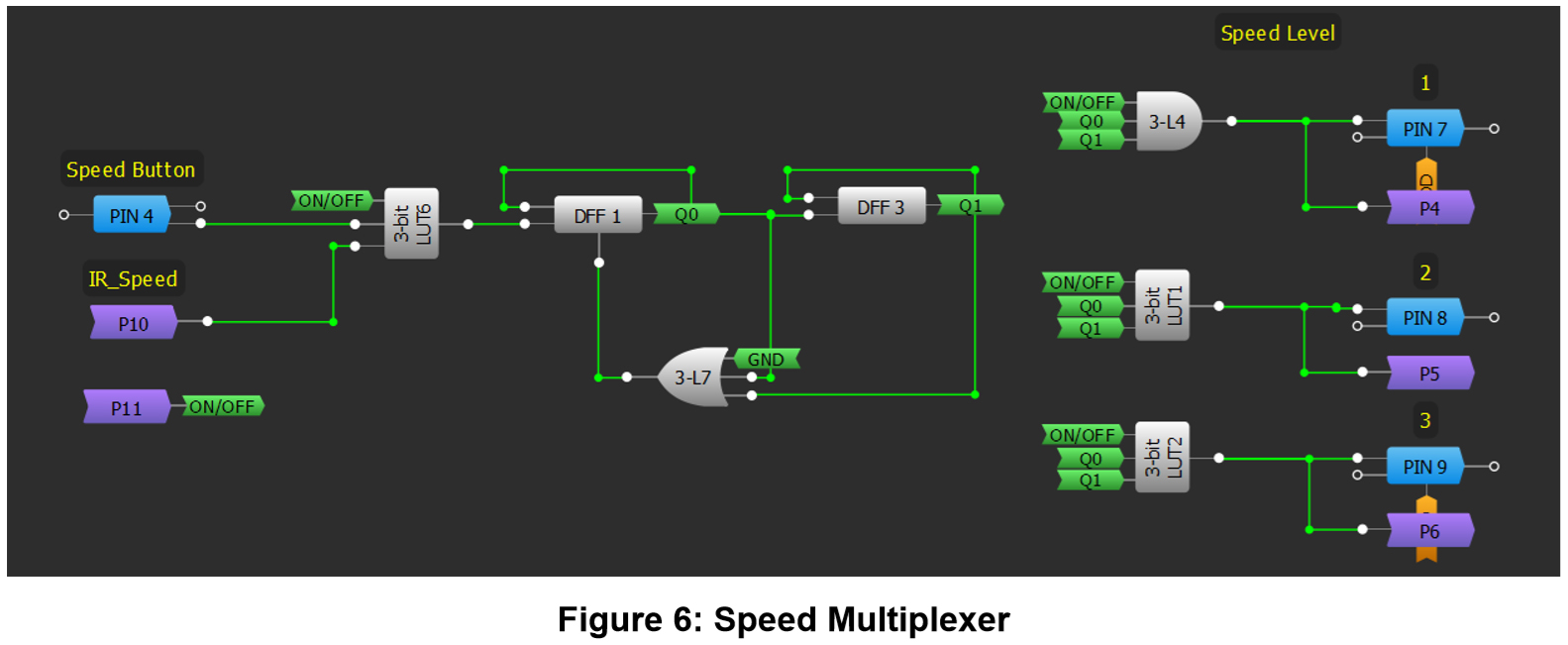
To switch speeds, a 2-bit binary counter was built whose input pulse is received by the external button which is connected to Pin4 or from IR speed signal through P10 from the command comparator. In the initial state Q1Q0 =11, and by applying a pulse on the input of the counter from 3-bit LUT6, Q1Q0 successively becomes 10, 01, and then the 00 state. 3-bit LUT7 was used to skip the 00 state, given that only three speeds are available in the chosen motor. The On/Off signal must be High to activate the control process. Consequently, if the On/Off signal is Low, the activated output is disabled and the motor is switched off as shown in Figure 6.
6. Timer
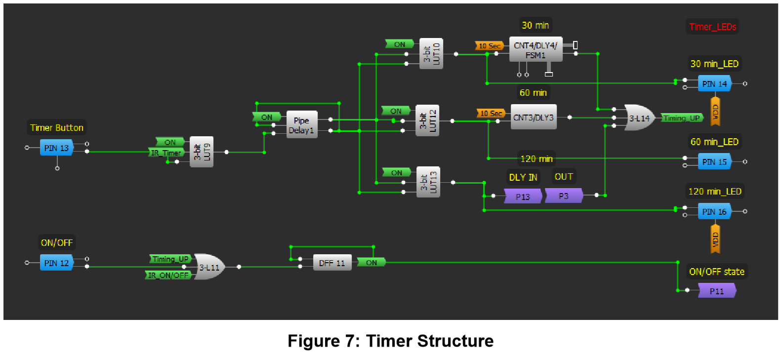
A 3-period timer (30 min, 60 min, 120 min) is implemented. To create the control structure a 2-bit binary counter receives pulses from an external Timer Button connected to Pin13 and from the IR Timer signal. The counter uses Pipe Delay1, where Out0 PD num equals 1 and Out1 PD num equals 2 by selecting an inverted polarity for Out1. In the initial state Out1,Out0 = 10, the Timer is disabled. After that, by applying a pulse on the input CK for Pipe Delay1, the output state changes to 11,01,00 in succession, inverting the CNT/DLY to every activated state. CNT0, CNT3, CNT4 were configured to operate as 'Rising Edge Delays' whose input originates from the output of CNT1, which is configured to give a pulse every 10 seconds.
To have a time delay of 30 minutes:
30 x 60 = 1800 seconds ÷ 10second intervals = 180 bits
Therefore, Counter Data for CNT4 is 180, CNT3 is 360, and CNT0 is 720. Once the time delay has finished, a High pulse is transmitted through 3L14 to 3L11 causing the system to turn off. The timers are reset if the system is turned off by the external button connected to Pin12 or by the IR_ON/OFF signal.
*You can use a triac or solid state relay instead of electromechanical relay if you would like to use an electronic switch.
* A hardware debouncer (capacitor, resistor ) was used for the push buttons.
7. Results
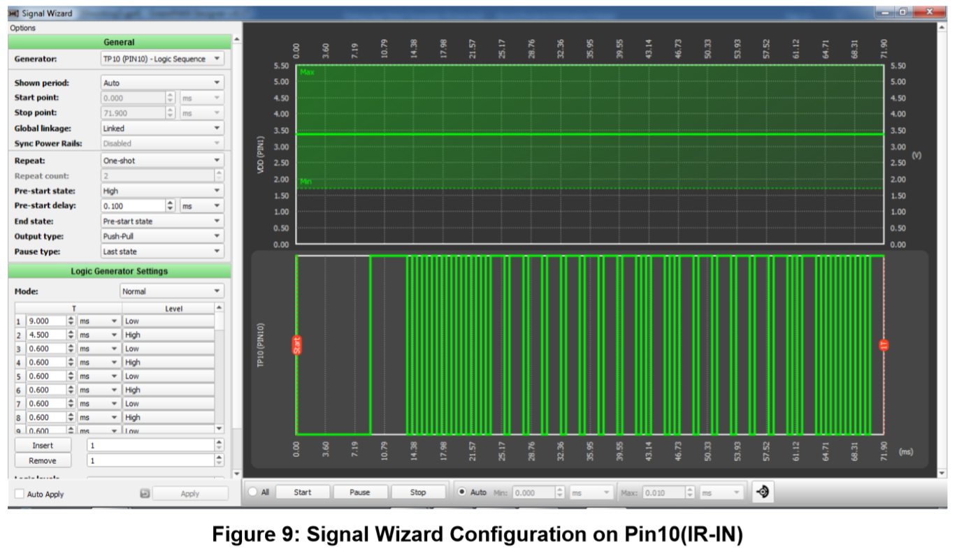
As the first step in the evaluation of the design, the GreenPAK Software Simulator was used. Virtual buttons were created on the inputs and the external LEDs opposite to the outputs on the development board were monitored. The Signal Wizard tool was used to generate a signal similar to NEC Format for the sake of debugging.
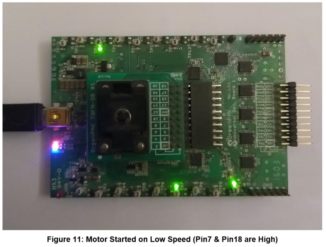
A signal with the pattern 0x00FF5FA0 was generated, where 0x00FF is the address corresponding to the inverted address stored in the PGEN, and 0x5FA0 is the command corresponding to the inverted command in DCMP register 3 to control the On/Off functionality. The system in the initial state is in the OFF state, but after the signal is applied, we note the system turns ON. If a single bit has been changed in the address and the signal was reapplied, we note nothing happens (incompatible address).
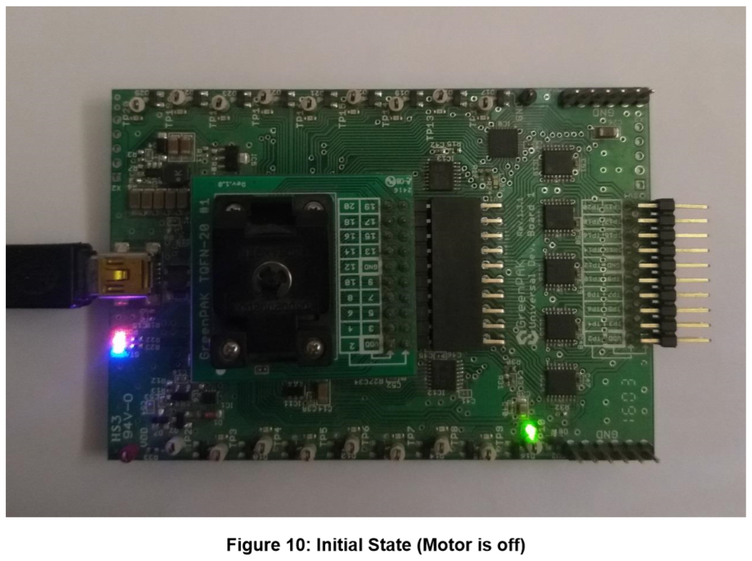
After starting the Signal Wizard for one time (with valid On/Off command):
Conclusion
This project centers on the configuration of a GreenPAK IC designed to control a 3-speed AC Motor. It incorporates a number of functions such as cycling speeds, generating a 3-period timer, and constructing an IR decoder compatible with the NEC protocol. The GreenPAK has demonstrated effectiveness at integrating several functions, all in a low cost and small area IC solution.