This project describes how to shift the frequency of a PWM signal without changing the duty cycle
Sometimes there is a need to change a frequency with retain a duty cycle. The following design allows changing frequency and retaining the duty cycle.
Below we described steps needed to understand how the solution has been programmed to create the PWM frequency converter. However, if you just want to get the result of programming, download GreenPAK Designer software to view the already completed GreenPAK Design file. Plug the GreenPAK Development Kit into your computer and hit the program to design the device.
How it works?
This design is designated to change the input frequency without loss of the duty cycle value. It only allows to do that for one constant frequency.
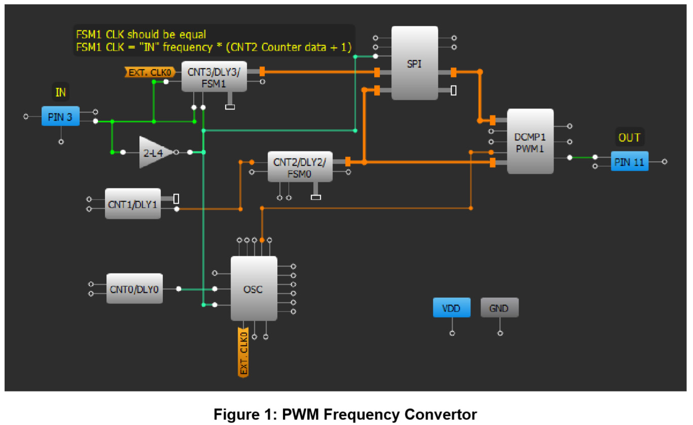
Let’s see how it works. When PIN#3 goes HIGH, FSM1 is reset by the rising edge and starts to count UP, thus measuring the pulse width. Then, when PIN#3 goes LOW FSM1 stops and falling edge at PIN#3 through invertor 2-L4 writes FSM1 counter value into SPI buffer. This operation is repeated each period.
At the same time, CNT2 just counts input frequency from CNT1. The counter value of CNT2 all time is compared with SPI buffer’s value by the DCMP1. The frequency at “OUT” is equal to output frequency of CNT2. To change the “OUT” frequency input frequency of CNT2 should be changed. Namely, CNT1 counter data can be changed, oscillator divider can be changed, type of OSC can be changed, also input frequency can be taken directly from OSC or external oscillator.
The input frequency of FSM1 (FSM1 CLK) should be selected using following formula:
FSM1 CLK = “IN” frequency × (CNT2 Counter data + 1)
“IN” frequency – frequency at PIN#3
If CNT0 counter data is 255, the formula can be written as:
FSM1 CLK = 256 × “IN” frequency
To change the FSM1 CLK, CNT0 counter data can be changed, oscillator divider can be changed, type of OSC can be changed, also CNT2 counter data can be changed.
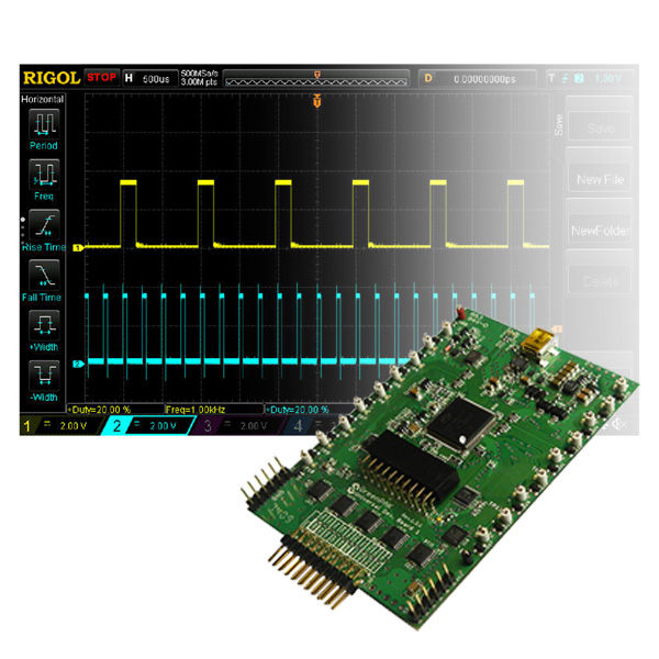
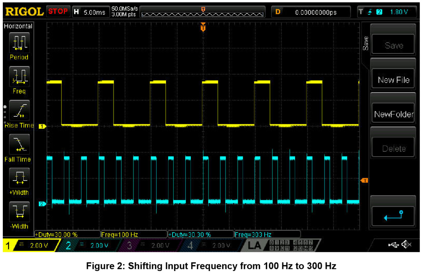
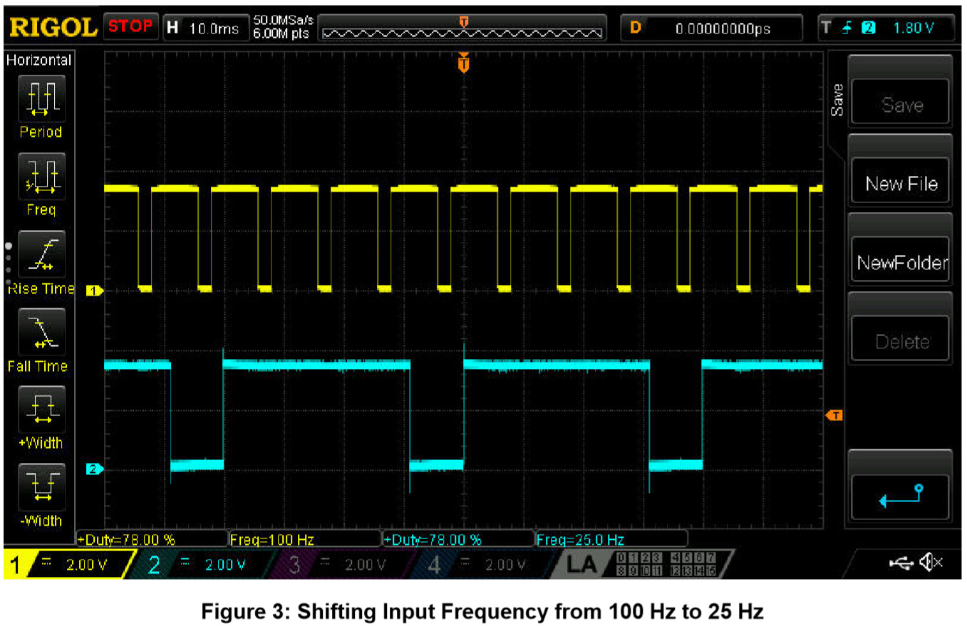
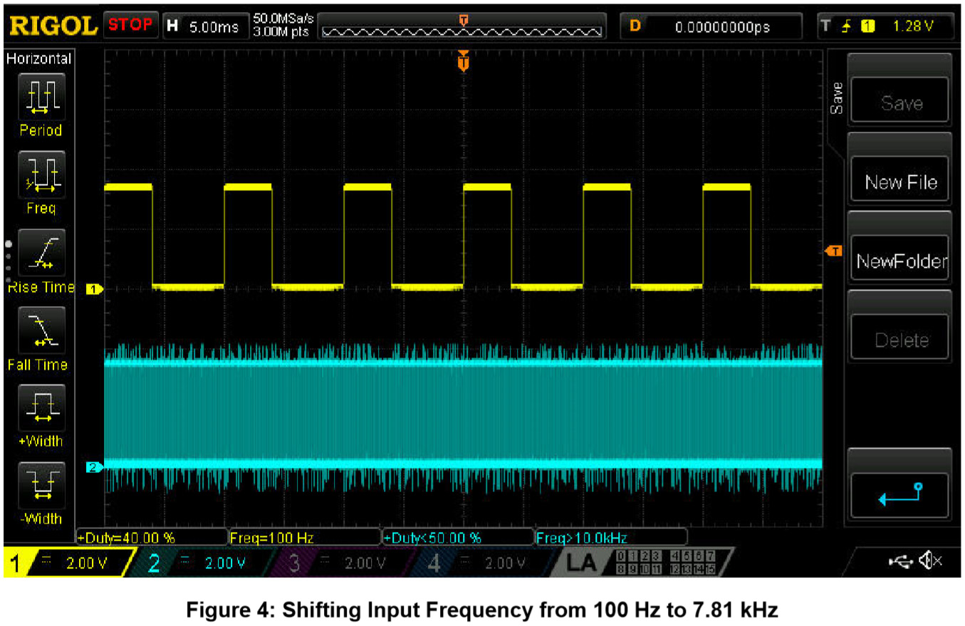
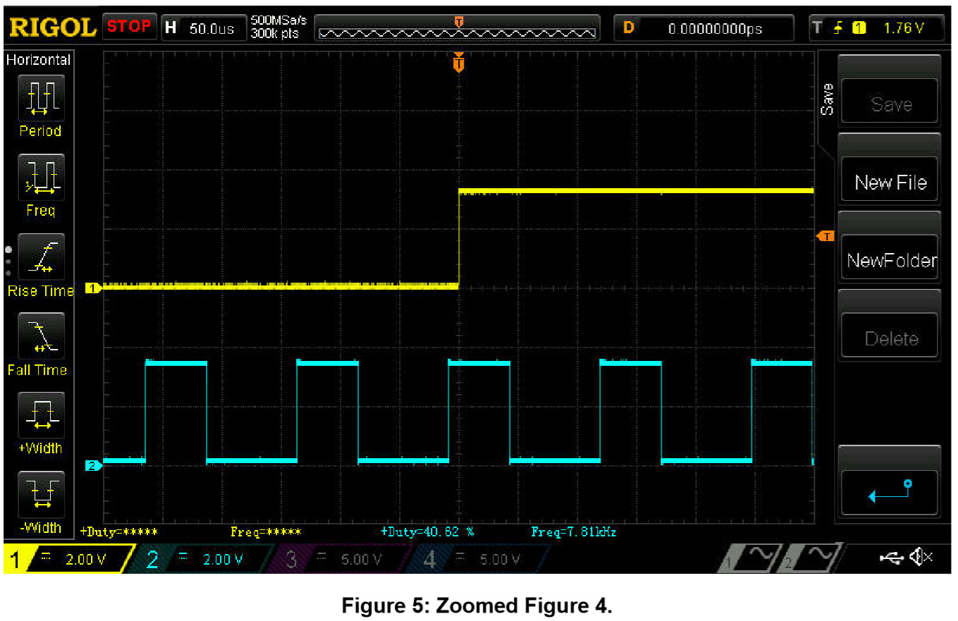
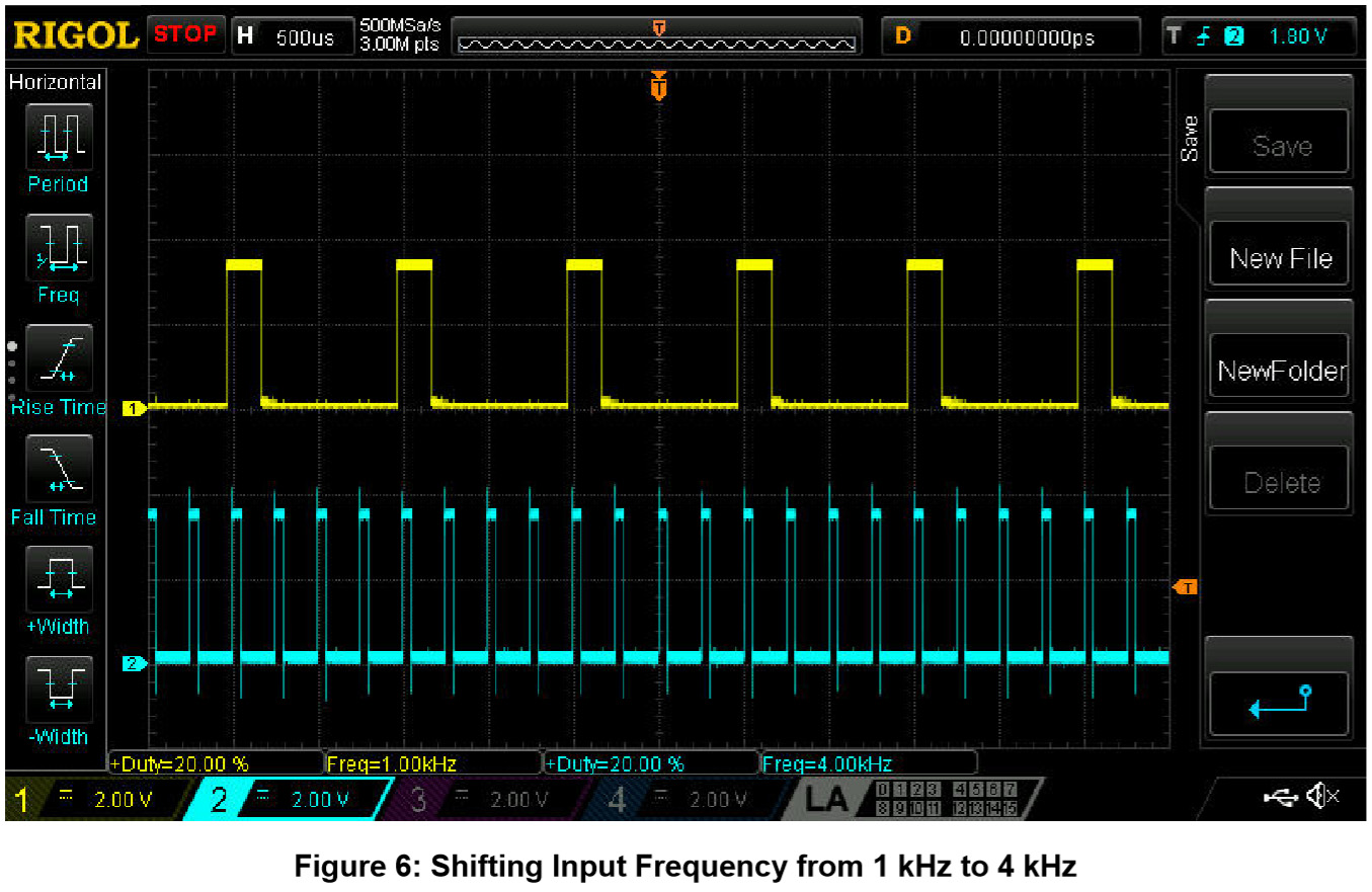
Below are shown several scope shots of the design’s functionality.
Channel 1 (yellow/top line) – PIN#3 (IN)
Channel 2 (light blue/2nd line) – PIN#11 (OUT)
Conclusions
This design can be used in many projects where there is a need to change a constant input frequency without loss of the duty cycle, for example LED backlight, motor controller, voltage regulator etc.