This project focuses on using a GreenPAK SLG46531V IC device to regulate an active solar tracker.
Solar Trackers are a type of device that follow the movement of the sun as it traverses from east to west each day. Solar Trackers are used to keep solar collectors/solar panels oriented directly towards the sun, as the sun moves through the sky. Using Solar Trackers increases the amount of solar energy received by the solar panels and improves the energy output of the heat/electricity which is generated. Solar Trackers can increase the output of solar panels by 20-30%, which improves the economics of the solar panel project.
Solar Trackers are mostly used in ground mounted solar farms with an energy-harvesting capacity greater than 1 MW. It is more difficult to use solar trackers on residential rooftop installations. Horizontal single axis trackers are typically used for large distributed generation projects and utility scale projects.
Active trackers use motors and gear trains to direct the tracker as commanded by a controller, responding to the solar direction. Since the motors consume energy, one wants to use them only as necessary.
Below we described steps needed to understand how the solution has been programmed to create the solar tracker. However, if you just want to get the result of programming, download GreenPAK Designer software to view the already completed GreenPAK Design file. Plug the GreenPAK Development Kit into your computer and hit the program to design the device.
1. Types of Active Trackers
Single axis trackers have one degree of freedom that acts as an axis of rotation. The axis of rotation of single axis trackers is typically aligned along a true North meridian. It is possible to align them in any cardinal direction with advanced tracking algorithms. There are several common implementations of single axis trackers.
Dual axis trackers have two degrees of freedom that act as axes of rotation. These axes are typically normal to one another. The axis that is fixed with respect to the ground can be considered a primary axis. The axis that is referenced to the primary axis can be considered a secondary axis. There are several common implementations of dual axis trackers. They are classified by the orientation of their primary axes with respect to the ground.
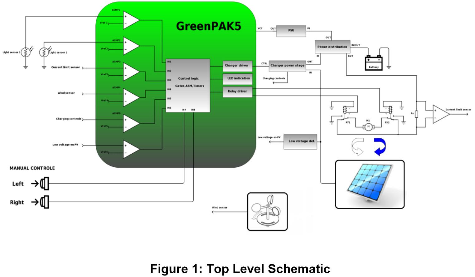
The single axis solar tracker is realized by the Dialog GreenPAK, shown in Figure 1.
2. Single Axis Solar Tracker with Integrated Voltage Regulator for Charging
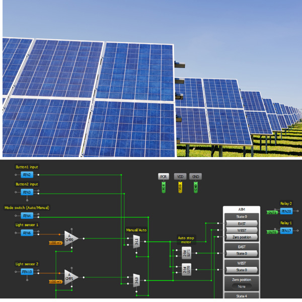
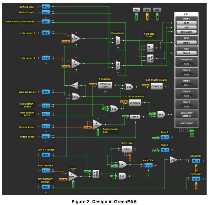
Figure 2 shows the GreenPAK SLG46531V realization of the logic for a single axis solar tracker. The schematic is segmented to compartmentalize the discrete functions.
The main purpose of this circuit is to control the motor that will turn the solar panels so that the sun rays fall directly onto the panel’s surface, thereby producing the maximum possible amount of electrical energy.
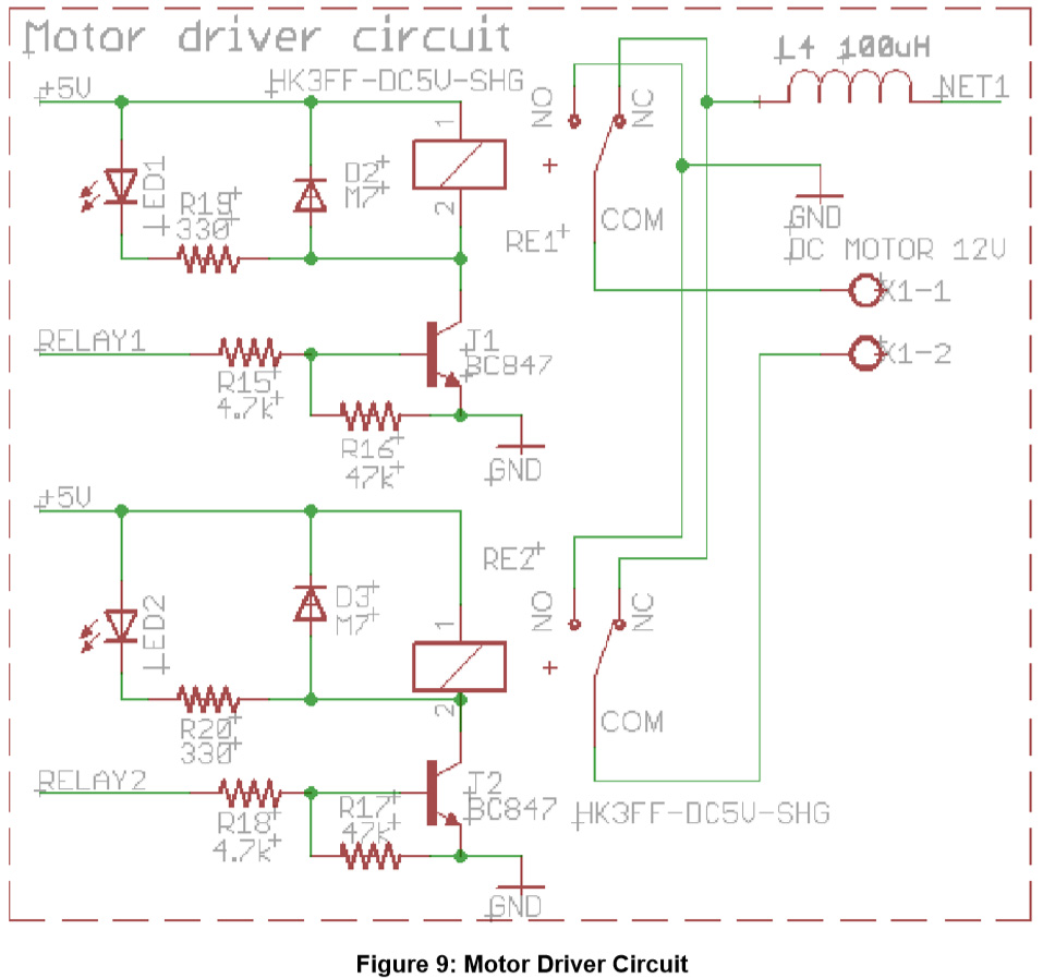
3. Rotation of the Solar Panels Using a Motor Driver
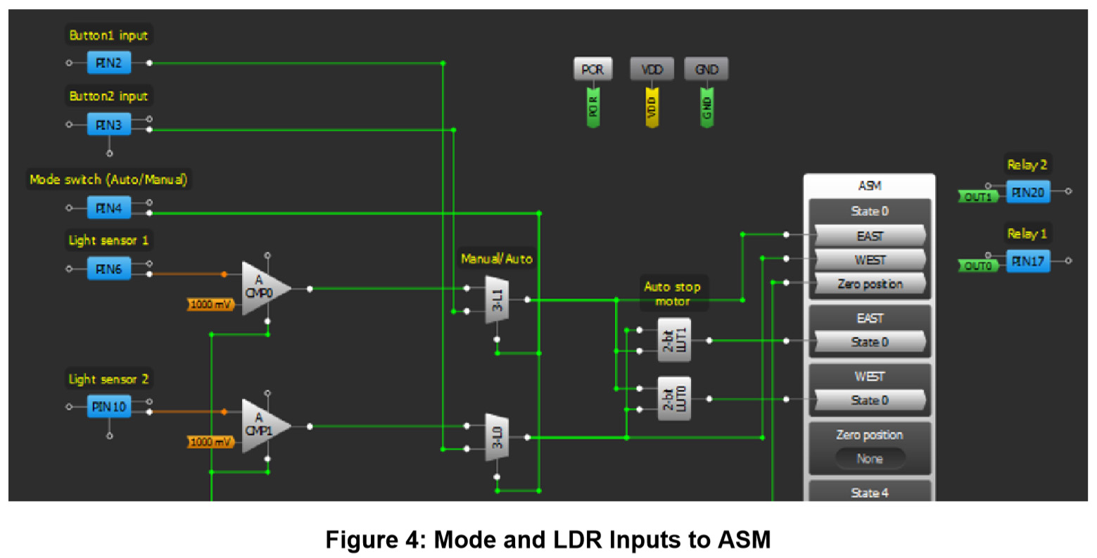
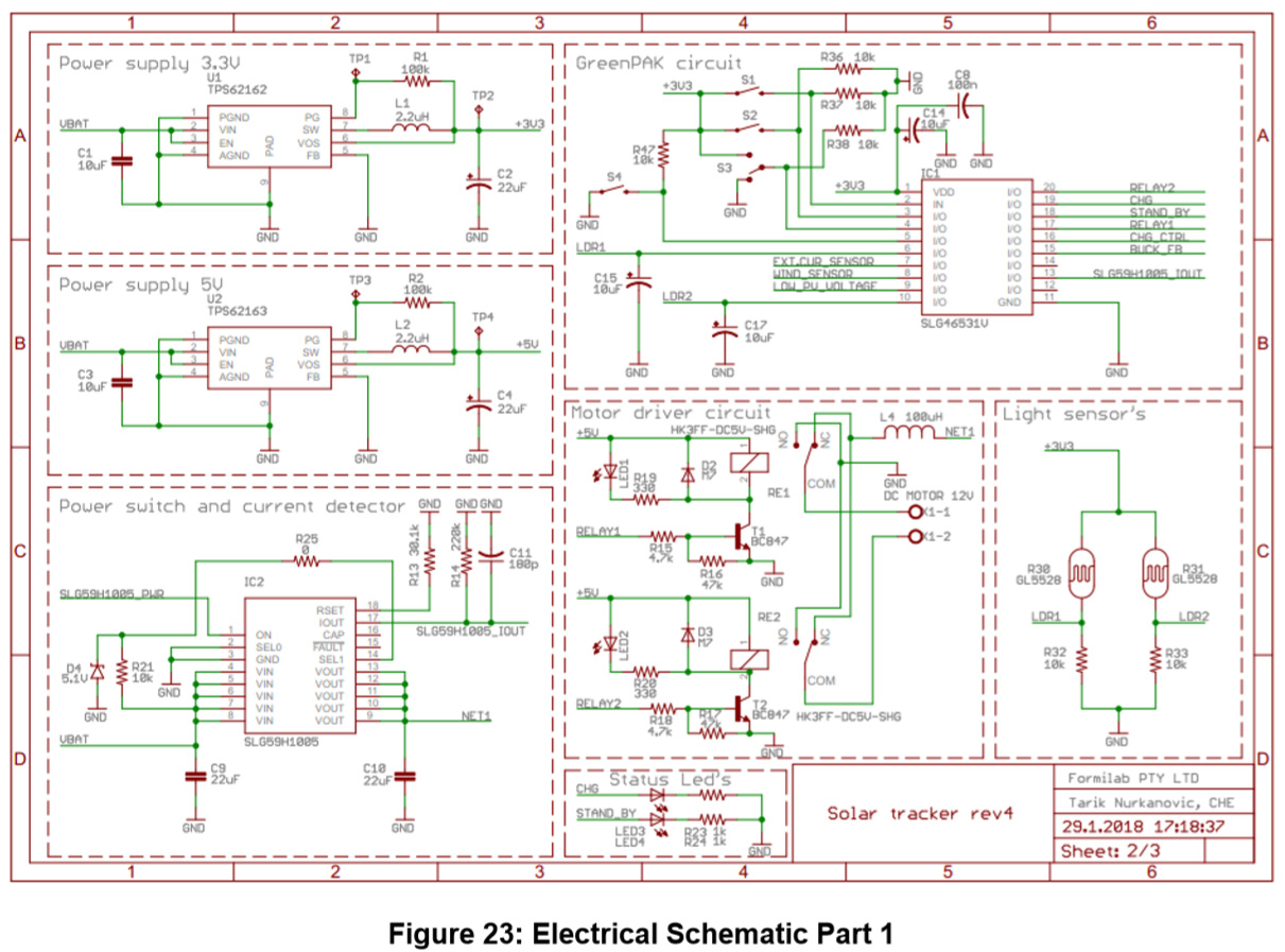
Moving the motor drive can be done manually by using the test buttons 1 and 2, which directly input their signal to the GreenPAK. Alternatively, light sensors 1 and 2 generate signals on which the GreenPAK's logic arbitrates to which side the panel should turn. The mode in which the GreenPAK operates (manual or auto) depends on the state of PIN4, which can be logic 0 or logic 1. The mode is determined by an external switch.
Light sensor 1 (PIN6), Light sensor 2 (PIN10), Button 1 (PIN2) and Button 2 (PIN3) represent the inputs into the GreenPAK which are necessary to turn the panel. The outputs of the GreenPAK used to control the motor driver are outputs from the GreenPAK’s ASM. The motor driver is made by two relays which are controlled by the GreenPAK.
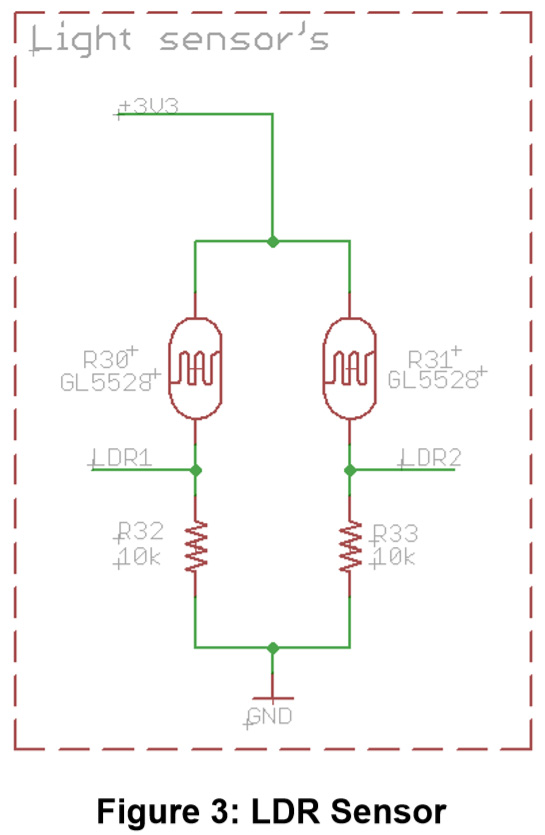
LDRs are used for light sensors (Figure 3). A Light Dependent Resistor, or photo-resistor, is a passive electronic component whose resistance lowers with an increase in light intensity.
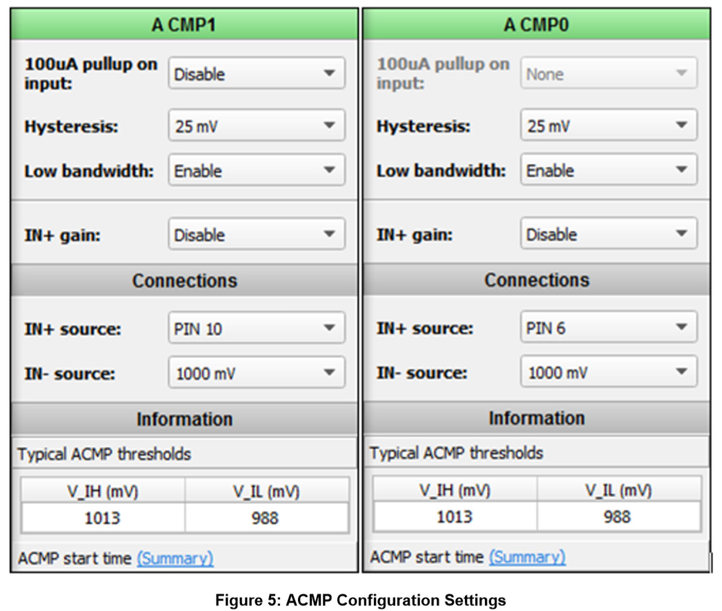
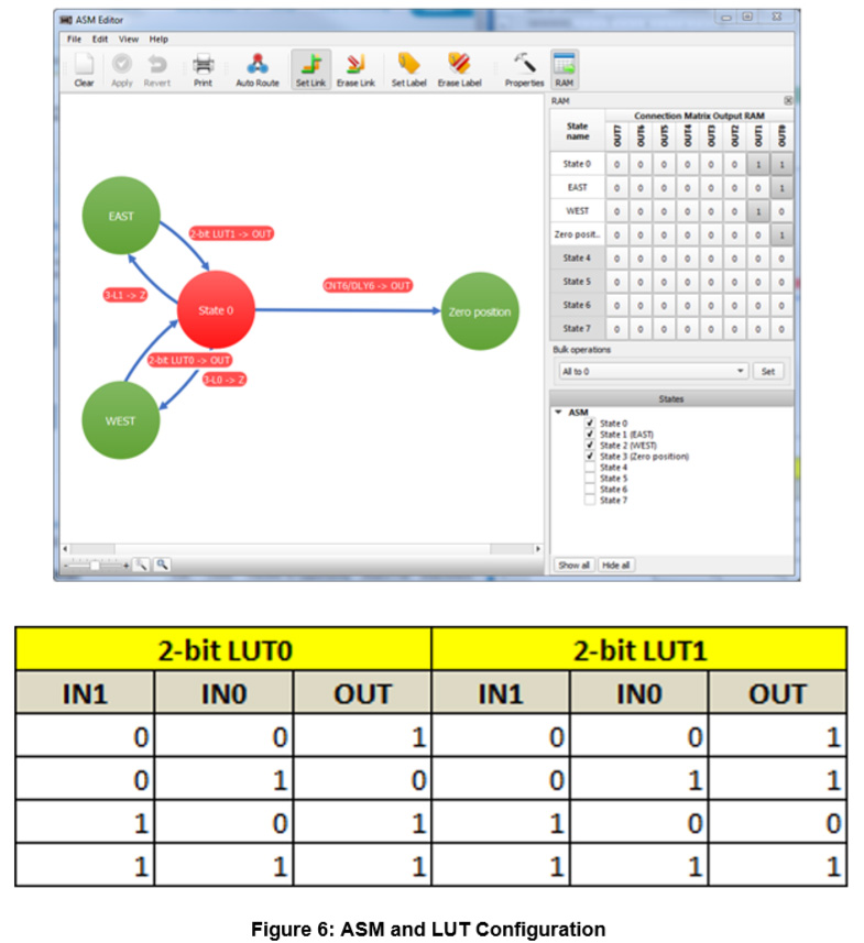
Figure 4 shows the input of PIN4, which is used to select between manual or auto motor control modes. When the manual mode is selected, MUXs 3-L0 and 3-L1 pass the signals generated by the test buttons 1 and 2. Those signals trigger corresponding states in the ASM, after which the ASM generates corresponding output signals that control the motor driver. By choosing Auto mode, MUXs 3-L0 and 3-L1 pass the signals generated by ACMP0 and ACMP1, which generate signals depending upon the state of the LDR's output. There is an option to turn off the Auto mode by turning off ACMP0 and ACMP1 using the fault detection outlined further in the note. LUT0 and LUT1 are used to set the ASM to a default state. Motors will only stop moving when the ASM is in state0.
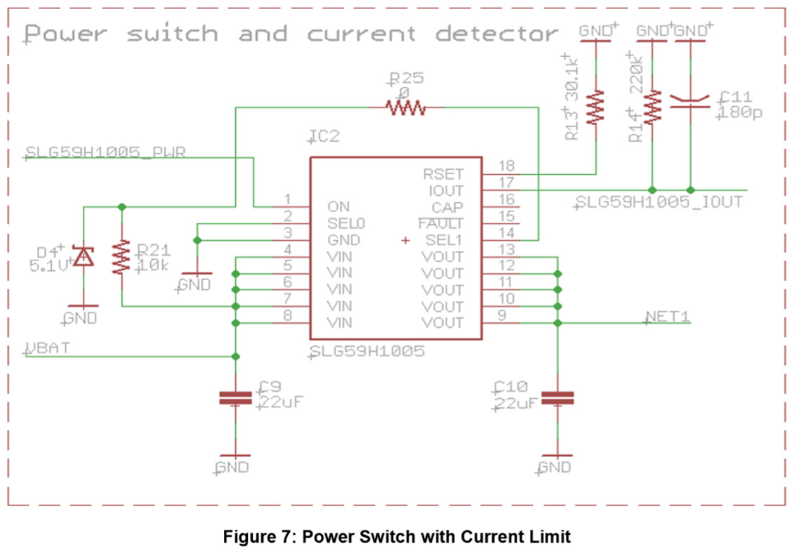
Although 2-bit LUT0 and 2-bit LUT1 can trigger the ASM to change to State0, it is also possible to reset the ASM by using a HIGH (logical 1) signal at nRESET IN of the ASM. This stops the motor when the panel moves to one of the end positions (limit switches). When position switch is pressed the ASM will reset and go to state 0. The stopping in both cases (east and west end positions) is implemented in the same way. This system also has the ability to prevent motor overload. In case the motor that moves the solar panel gets stuck for some reason, IC2 (SLG59H1005, see Figure 7) will detect that the current passing through the motor has passed the set current limit and it will send a signal to GreenPAK that will turn the ASM off, and thus the motor will be turned off as well.
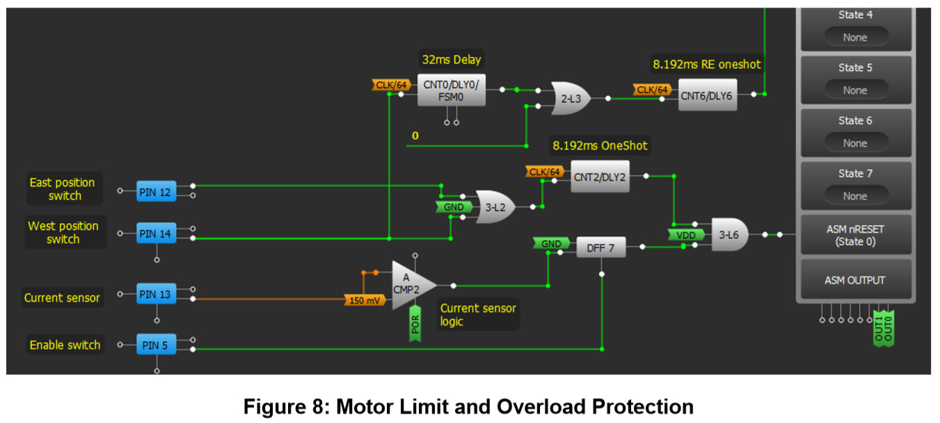
Running the system again is possible by pressing the switch that is connected to PIN5. Figure 8 shows the logic of motor stopping in end positions and motor overload prevention.
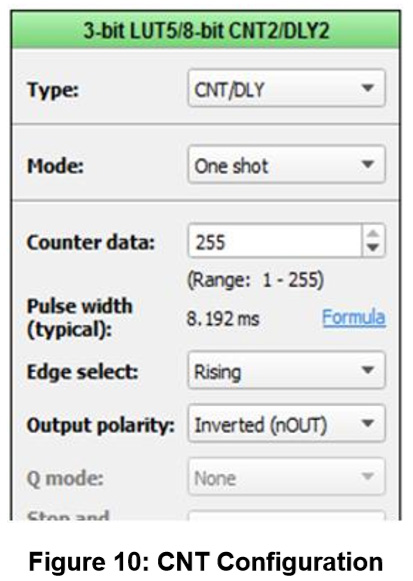
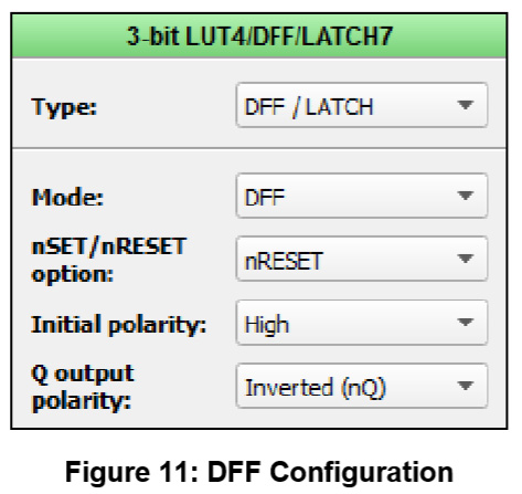
In order for the ASM to function, nReset pin has to be HIGH . When the system is turned on, initial states DFF7 and CNT2/DLY3 are set as logic 1 (HIGH). CNT2/DLY2 is also set as OneShot. It's clear from looking at the image that all inputs of AND logic circuit are logic 1, and as a result we have logic 1 on ASM nReset. Let's assume that the solar panel is somewhere on the way between east and west limit switches and that it's moving towards west limit switch. When it triggers west limit switch, the change from LOW to HIGH will happen on pin 14. That change will be transferred over OR logic circuit to OneShot blockCNT2/DLY2 input which will generate a change from HIGH to LOW and reset the ASM. ASM will then switch to State 0 and the motor will stop. We can see that block DLY0 is also connected to PIN 14.
32 ms after the change from LOW to HIGH on PIN14 happened, DLY0 will activate OneShot block CNT6/DLY6, which will generate a signal and switch ASM to State Zero position. The State Zero position has the command for the panel to turn towards east, that is, to return to starting position and wait for sunrise. When the solar panel triggers East limit switch, it will also trigger OneShot block CNT2/DLY2 through OR logic circuit. OneShot block CNT2/DLY2 will generate a signal for resetting ASM and it will set ASM to State 0 and the motor will stop. In case the motor gets stuck during its operation it will draw more current. Exceeding of the limit for current through the motor will be detected by IC2 that will generate a signal to PIN13 and ACMP2. That signal will change the state of DFF7. DFF7 output will be LOW and it will disable ASM, and thus the motor as well.
ACMP2, CNT2/DLY2, DFF7 and 3-L6 are used to implement the reset logic of the ASM. CNT2/DLY2 is set to work in one shot mode to generate only one pulse, no matter how long the voltage of logic unit that is generated by external circuit is presented on the input of DLYIN.
Output IOUT of circuit SLG59H1005 is externally connected to PIN13 of the GreenPAK. Depending on the current through the motor, that is, through SLG59H1005 on IOUT, we'll have a voltage equivalent to current according to the equation:
VIOUT =RIOUT * 10uA/A
Where RIOUT is resistor between GND and pin IOUT of the SLG59H1005 circuit.
In addition to using this circuit for measuring the current through the motor, the design also implements a power controller for the motor. If the voltage on a panel is below a certain level the motor's power supply is lost.
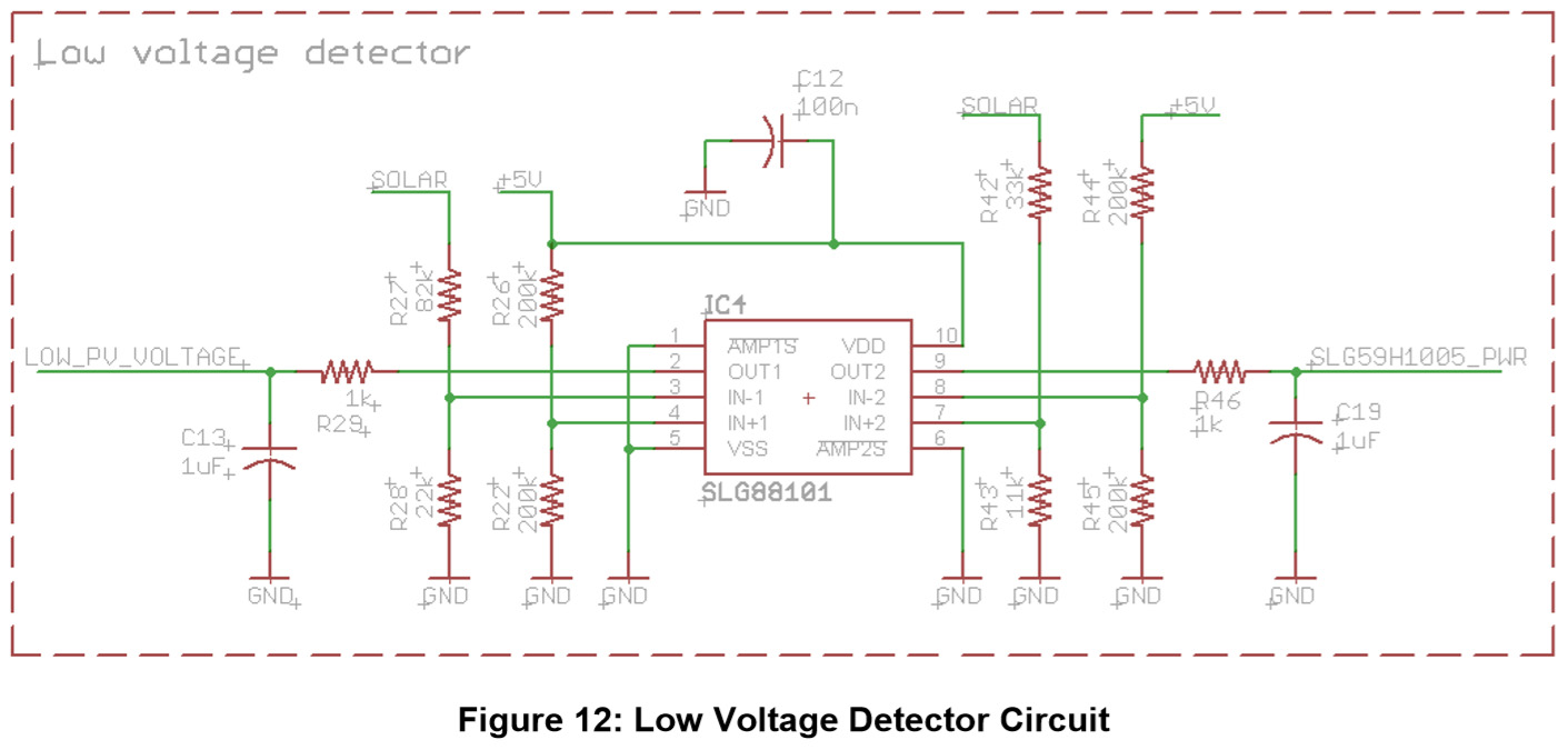
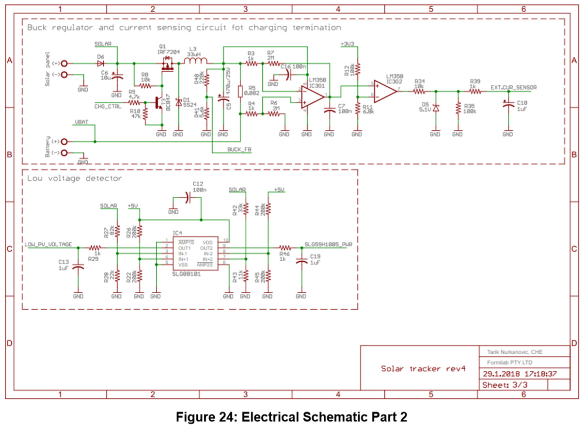
When the sun starts setting and the panel has come to its end position by following the sun, the voltage on the panel starts to decline and the low voltage circuit, shown in Figure 12, will detect when the voltage drops below a certain level and will generate an output signal which will lead to PIN9 of GreenPAK. This signal is used to return the panel to the default position (east end).
IC4 is low power dual amplifier, where AMP1 detecting low voltage, AMP2 cut off power for motor.The voltage threshold in “AMP1” is higher than the voltage threshold in “AMP2” because the motor needs power to move the panel to the default position before SLG59H1005 cuts the motor's power supply entirely. Also, when the voltage on the panel is below certain level, auto control of the motor moving the panel is disabled. This is achieved by turning off ACMP0 and ACMP1, which will then not function regardless the sensor state.
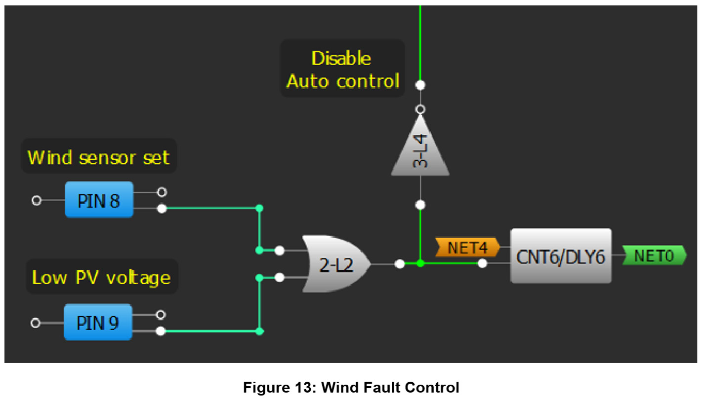
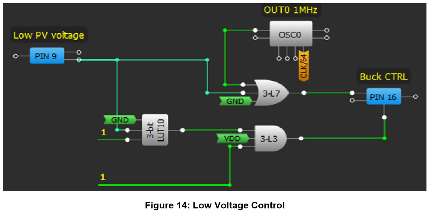
If the external circuit detects a voltage drop on a panel, regardless of the OSC0 oscillator's output, PIN16 keeps the MOSFET ON in the power stage of the buck regulator and passes the voltage to the solar panel. If the panel is in a position different than its initial position, CNT6 will generate a pulse that will trigger the ASM to change into state0, and the panel will go back to the default position. This also happens when the low voltage or wind faults (PIN9 or PIN8) signal HIGH.
Strong winds can damage the panel's system. Consequently, there is an option to add a wind sensor to this system. The sensor provides information about wind speed and is input into Pin8.
4. Buck (step-down) Regulator
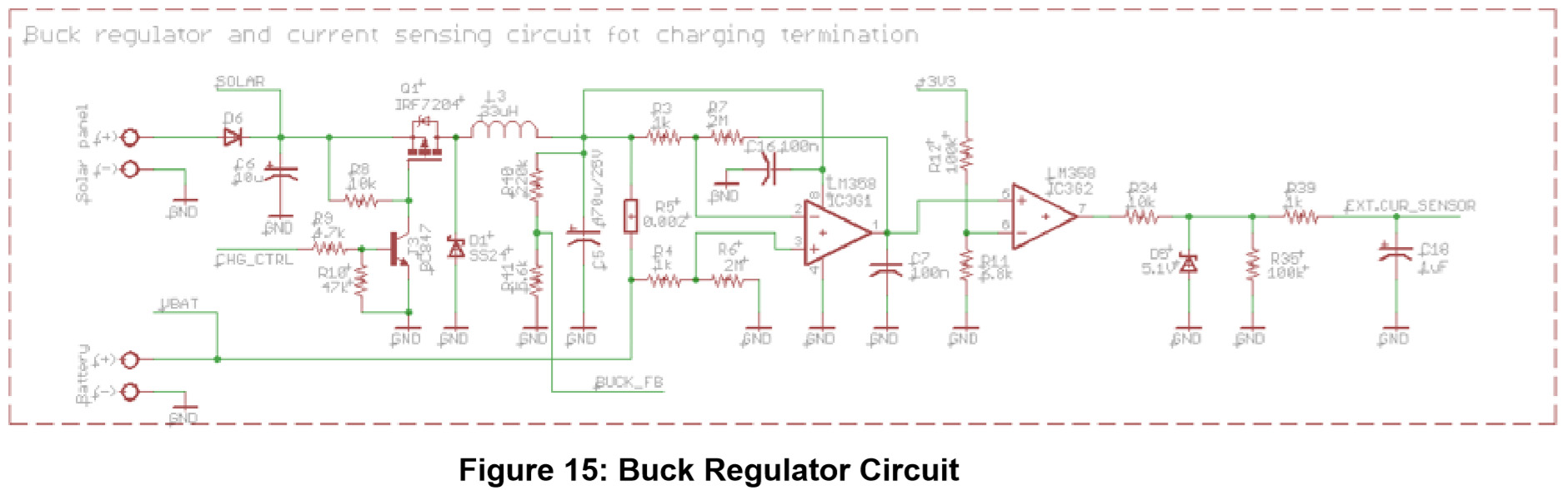
The amount of current generated by a solar panel is dependent upon the intensity of light that falls on the solar panel’s surface. Therefore, it's not desirable to charge the battery directly from the panel, the voltage needs to be regulated. A buck regulator is used to regulate the voltage for charging the battery. The battery is charged in Constant Voltage (CV) mode, that is, the output voltage of the regulator is kept constant even if the voltage on a panel rises. The reason for CV mode is to prevent overcharge.
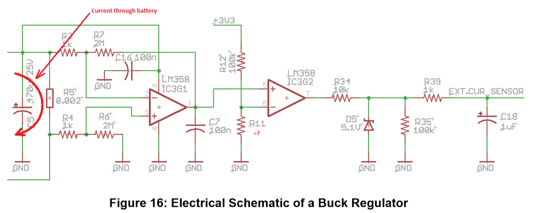
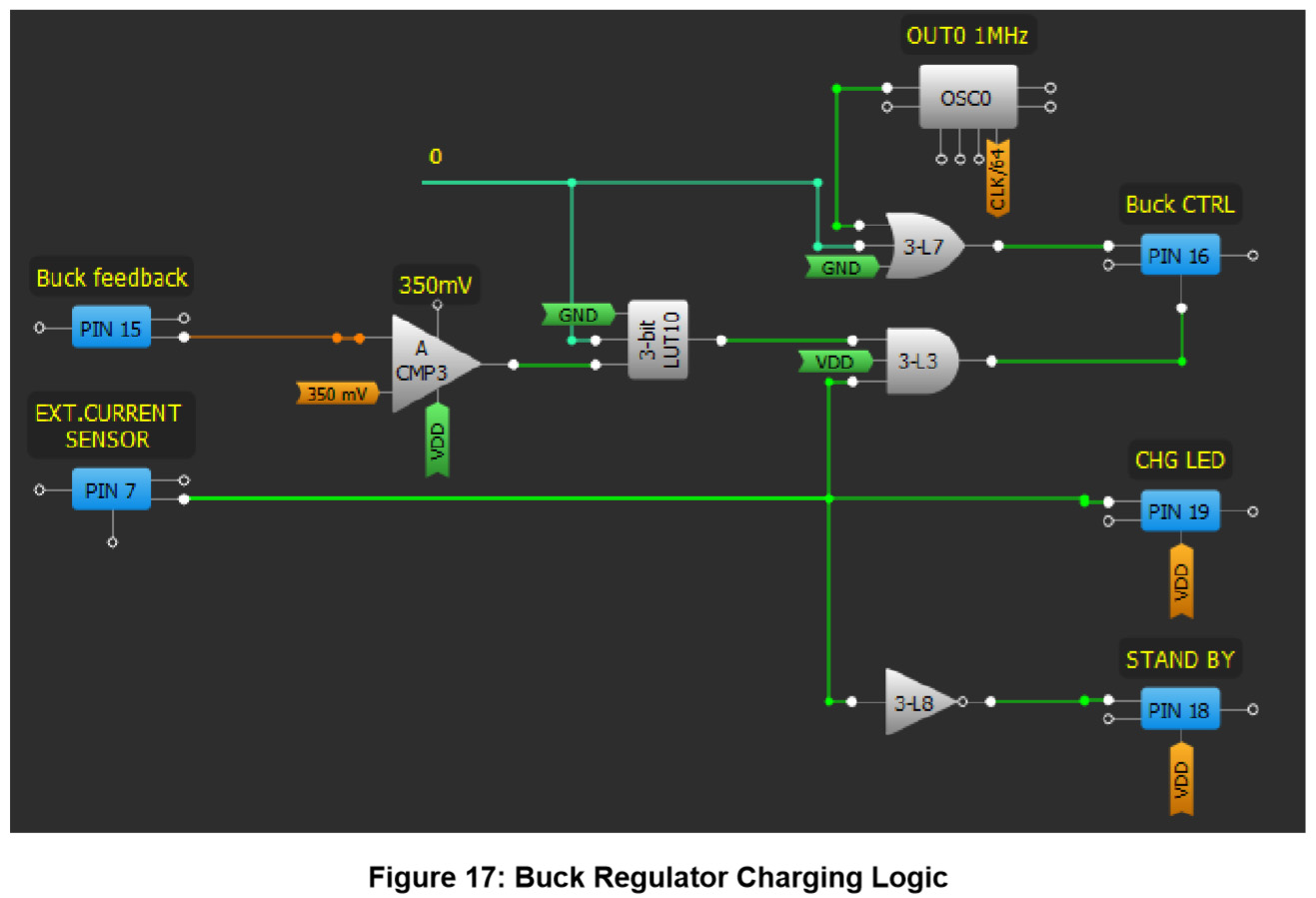
Figure 16 shows an electrical schematic of a buck regulator with circuitry for measuring the charging current. The measured charging current determines when to terminate the process of charging the battery. Figure 18 highlights the logic of Buck regulator.
5. Circuit for Terminating the Process of Battery Charging
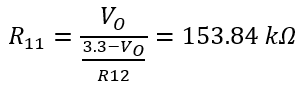
The circuit for terminating the charge process consists of two stages that are realized with LM358 operational amplifiers. The first stage of this circuit consists of sensing the current through resistor R5 (at any given time the current through R5 is equal to current of battery charge). The first stage then converts the voltage that leads to the input of the voltage comparator at the beginning of the second stage. Resistors R11 and R12 define the current at which the process of charging is terminated. Amplifying the first stage is G=2000. If the current falls below 500 mA the charging process is finished. R12 is set at 100k and R11 is calculated. The following equations are also calculated:
VR5 = R5 * IBAT = 0.002Ω * 0.5 A = 0.001 V, VR5 - voltage onR5, IBAT-current through battery
VO = G * VR5 = 2000 * 0.001 * 2000 V = 2 V, output voltage of the first stage
6. Buck Regulator – GreenPAK Logic and Calculations
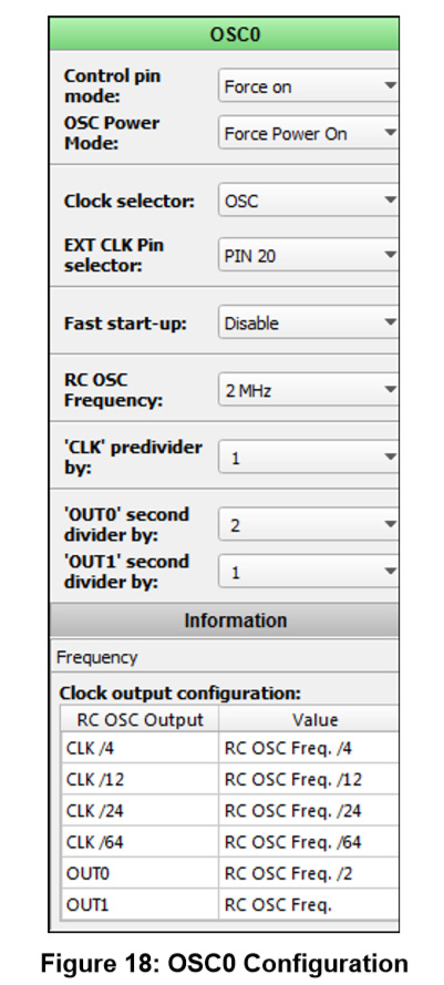
If the circuit output for terminating the charging process (PIN7) is HIGH, the battery needs to be charged. PIN16 directly controls the top gate MOSFET in the buck regulator. Pin 16 is arbitrated by the buck feedback and external current sensor. Using OSC0 as the clock ensures consistency for the power stage, duty cycle and frequency. Using these two parameters and other needed parameters the calculated value of the components for the buck power stage are shown:
D = 50%, duty cycle
fs = 1MHz, switching frequency
IOUT(max) = 3A, output current
VOUT = 14.0 V, desired output voltage
η = 85%, efficiency of the converter
ΔVOUT = 500mV, desired output voltage ripple
VIN(max) = VOUT / (D*η) = 32,94 V, max. Input voltage
∆IL = (0.2 to 0.4) * IOUT(max) = 0.2 * 3A = 0.6A, inductor ripple current
Lmin = VOUT*(VIN(max)-VOUT) / (ΔIL*FS*VIN(max)) = 13,41uH , min. inductor value
ISW(max) = IOUT(max) + ∆IL/2 = 3,3A , max. switching current
COUT(min) =∆IL/(8*ΔVOUT*fs)⩳ 1uF , min.output capacitance
IF = IOUT(max) * (1-D) = 1,5A , diode forward current
PD = IF * VF = 0.75W , diode power disipation
Based on calculated parameters for buck power stage it is possible to choose components, coils L, MOSFET, the output capacitor, and diodes.
Based on calculated parameters for buck power stage it is possible to choose components, coils L, MOSFET, the output capacitor, and diodes.
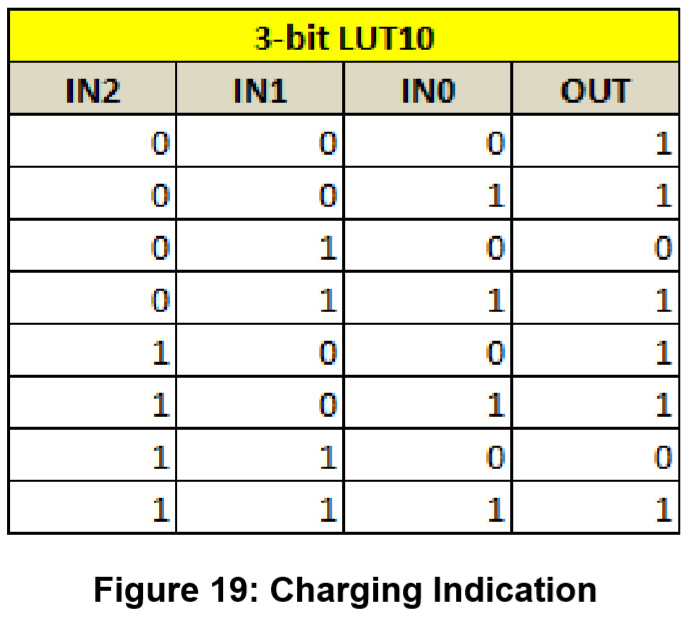
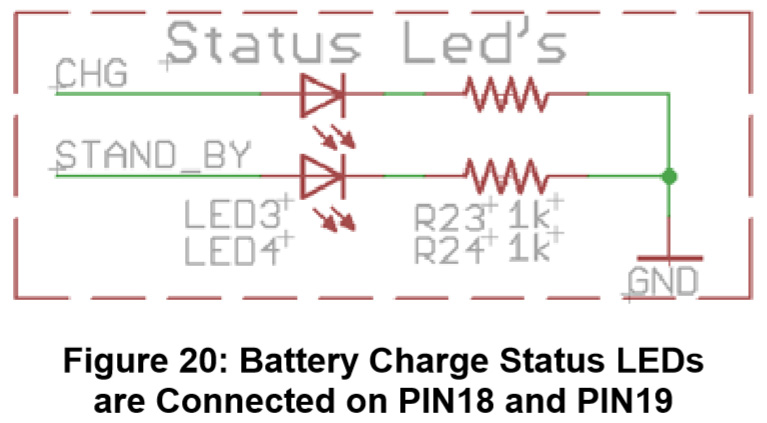
Battery charge status LEDs are connected on PIN18 and PIN19.
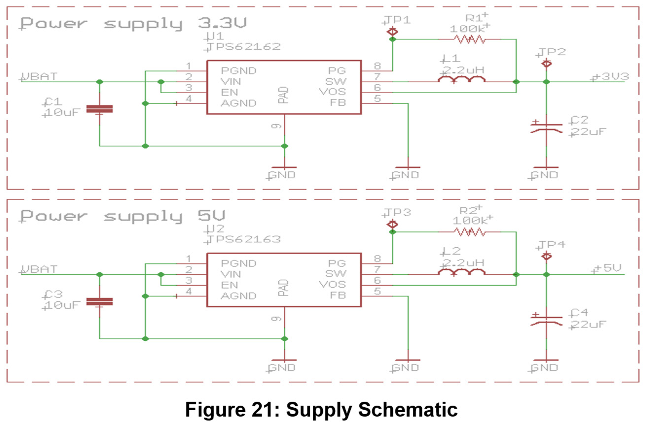
Electronic circuits used for realization of this assembly nominally require a supply of +5 and 3.3 V. Figure 21 is the schematic of the supply circuit.
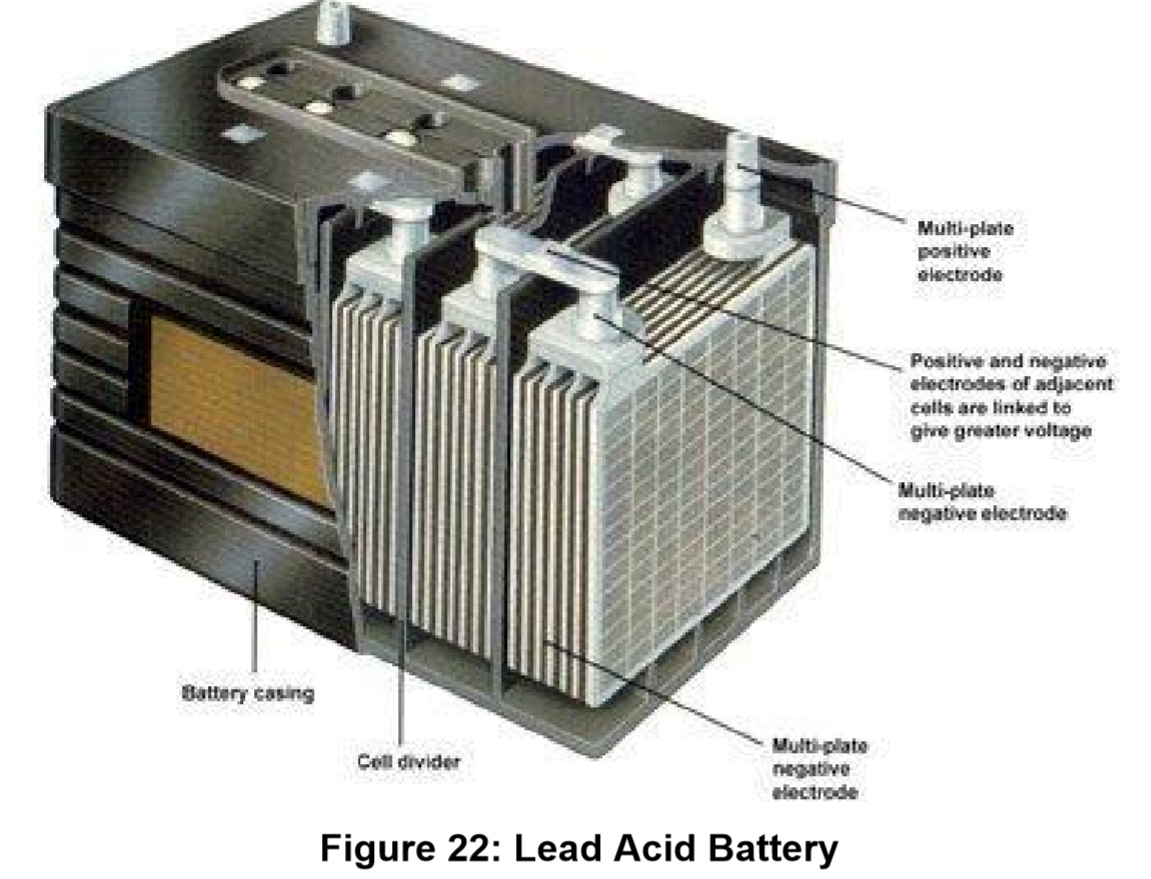
This system is adapted for charging the wet cell batteries that are more resistant to overcharge and don’t require a specific way of charging. By contrast, lead acid batteries would not be able to function with this charging configuration.
Conclusion
The proposed design and implementation show that the single axis solar tracker with voltage regulator can be realized using the SLG46531V GreenPAK. The single axis solar tracker itself is a combination of analog and digital techniques, which means that a significant number of analog and digital integrated circuits are needed for the assembly. By using GreenPAK it is possible to significantly reduce that number of circuits and thus reduce the size and cost of the product. Reducing the number of mentioned circuits significantly reduces the chance for any errors which results in a more reliable system, all thanks to Dialog's GreenPAK technology.