This project describes how to develop an elderly care alert system using GreenPAK SLG46533V
Below we described steps needed to understand how the solution has been programmed to create the fall detection circuit. However, if you just want to get the result of programming, download GreenPAK software to view the already completed GreenPAK Design File. Plug the GreenPAK Development Kit to your computer and hit the program to design the solution.
Introduction
In this project, we develop an elderly care alert system using GreenPAK SLG46533V. This fall detector/ panic button is a low-powered device so that it works for long periods of time. The panic button can be triggered manually by the elderly person and also it can detect a fall event and send an alert email to the concerned individuals. The panic button alarm/help call can be reset manually.
The circuit receives its inputs from ADXL335, a 3-axis accelerometer module. A brief introduction of the module is described below.
ADXL335 3-Axis Accelerometer Module
The ADXL335 is a small, thin, low power, complete 3-axis accelerometer with signal-conditioned voltage outputs. It measures acceleration within the range of ±3g. It can measure the static acceleration of gravity in tilt-sensing applications, as well as dynamic acceleration resulting from motion, shock, or vibration.
The module is powered with 3.3V DC and has 3 analog outputs which measure acceleration in 3-axis (x, y, z).
In the case of no acceleration the corresponding outputs read 1.65V.
If the device measures positive acceleration, the output values increase towards 3.3V; negative acceleration causes the values to decrease towards 0V. Since the Z-axis has acceleration due to gravity present at all times, z-output reads value equivalent of 1g (ideally 2.2V dc), i.e. its output is higher than X-output and Y-output when at rest (Fig.1).
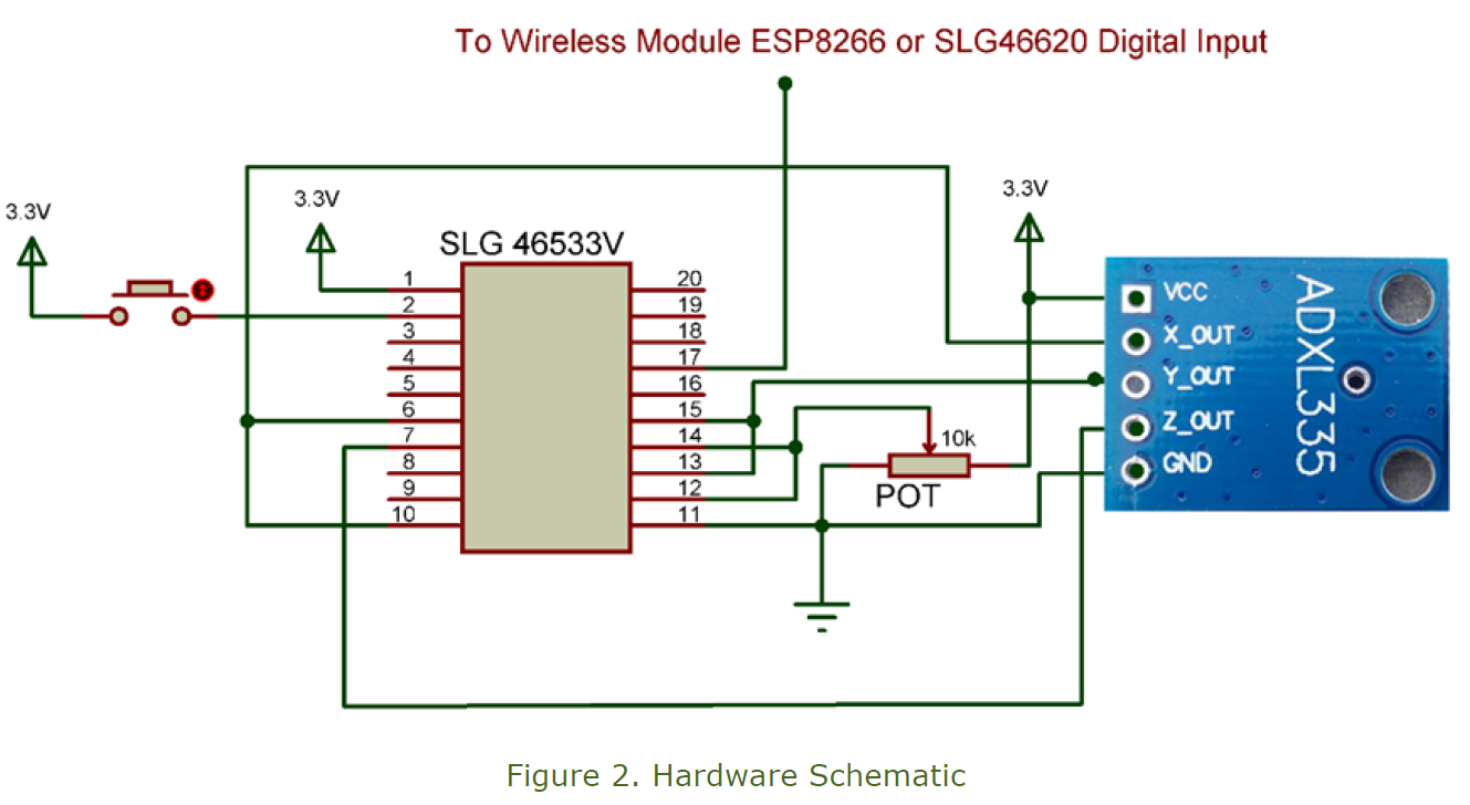
Hardware Schematic
The hardware schematic has the ADXL335 module connected with the SLG46533V. The 3-axis acceleration outputs are connected to analog input pins for GreenPAK comparators and are compared with the thresholds set in the GreenPAK code.
Thresholds are also set externally by the 10k potentiometer (Fig. 2).
GreenPAK Design Code
The design code consists of two types of acceleration surges: one for the X and Y axes and the other for the Z-axis.
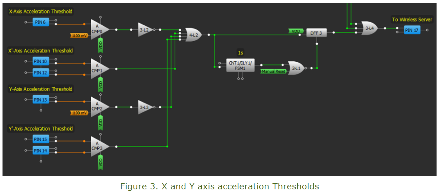
X and Y Axis Acceleration
If positive or negative acceleration increases on the X axis or Y axis in a short interval of time, it may indicate a fall. (The value can be adjusted according to the activity level of the elder.) The voltage due to the acceleration surge is compared with the threshold set in GreenPAK for ACMP0 and ACMP2, which are by default set at 1100mV which corresponds to -1g. The sensitivity of the fall sensor can be adjusted in the GreenPAK code by changing the IN- voltage of the analog comparators (Fig. 3).
For positive acceleration detection for the X and Y axes, a 10K potentiometer is set to set the IN-input of the analog comparators at the desired values (currently it is set at 2.2V, which corresponds to +1g).
If any of the four analog comparators detects an acceleration surge, it sets the DFF3 output high. If the surge is longer than one second it will be neutralized. The reason behind neutralizing longer surges is that it may reflect a continuous activity like walking, running etc. A fall event would generate a small surge of acceleration in any of these four axis (X, X’, Y, and Y’).
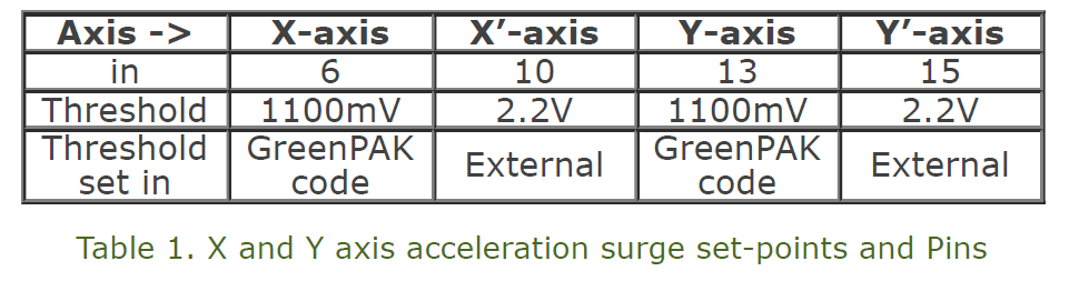
The hardware connections of these two axes with the GreenPAK design code is tabulated below (Table 1).
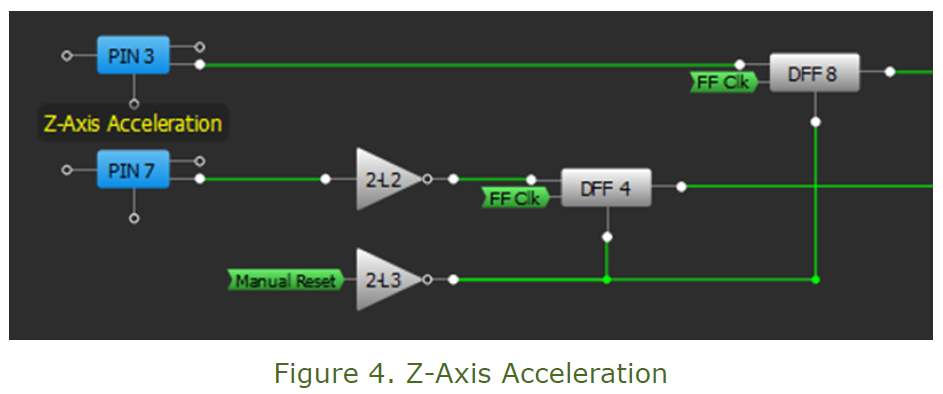
Z-Axis Acceleration
The Z-axis acceleration has a key role in determining whether a fall event has occurred. The Z-axis acceleration has a negative surge when impact occurs. This surge is large and it can alone be used to determine the fall event. The digital input Pin7 is used to determine this surge (Fig.4).
If any of the 5 surges described occurs, a fall would be detected and Pin 17 output is set high.
The output can be reset by the manual button attached at Pin 2. This can help in neutralizing the spurious fall signals. The fall signal or help signal can be manually initiated by pressing the button attached to Pin 3.
From here there are two different approaches to send this fall signal to some individual via email:
1. For more than two (and less than 8) input System
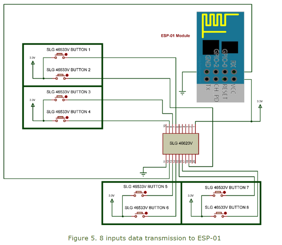
The output from 8 different GreenPAK SLG46533V’s can be connected to the internet via ESP-01 module and a GreenPAK SLG46620V.
The eight input signals are sent to the SLG46620V, which send them serially to ESP-01 which is used to email a specific address.
The ESP-01 module is configured to perform the following functions:
(i) It assigns a fixed IP to access the GreenPAK device (192.168.10.100 in this case)
(ii) It connects to a smtp2go server account
(iii) If any one of the inputs is triggered, an email is sent to the selected email address. The content of the email shows which input which has detected the fall/panic. For more than one fall event, the email contains the status of all the panic inputs which have been triggered.
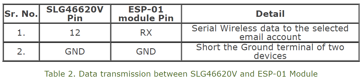
Data is transmitted serially from the SLG46620V to the ESP-01 module. The RX pin of ESP-01 is connected with Pin 12 of the SLG46620V. The ground signals of all the modules (ADXL335, ESP-01, SLG46533V and SLG46620V) are connected together.
The interface between the ESP-01 and SLG46620V is tabulated below (Table 2).
The hardware schematic of this part is shown in Fig.5.
GreenPAK SLG46620V Design code for sending 8 inputs data to ESP-01
The design code of SLG46620V consists of four parts:
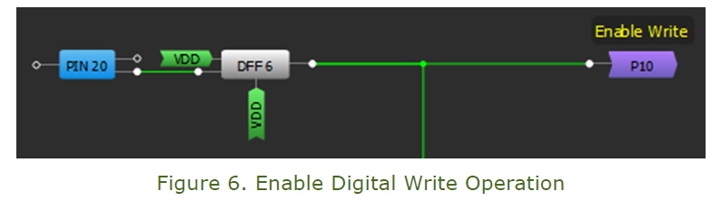
1.1 Enable Digital Write Operation
This part of the code enables the digital input write operation from GreenPAK SLG46620V to ESP-01 module. When PIN 20 is set high, it clocks VDD through DFF 6, which causes Enable Write to go high. The nReset pin is permanently high so that the DFF cannot be reset. The Enable Write signal is passed back to Matrix 0 through P10 (Fig.6).
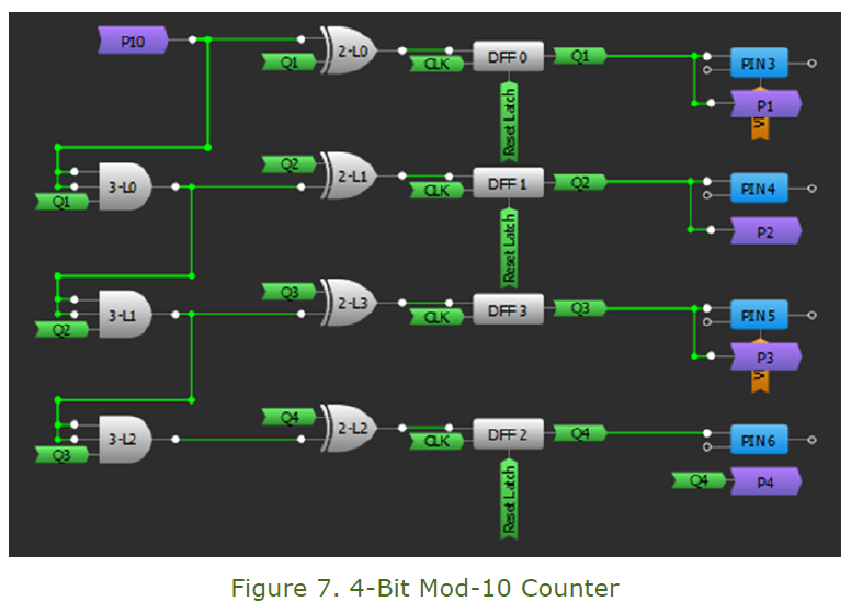
1.2 4-Bit Mod-10 Counter
Among the four outputs (Q4, Q3, Q2 and Q1) of the flip-flops, Q4 is the MSB and Q1 is the LSB. The circuit counts up to 10102 or 1010, then it is reset by the reset block (Fig.7).
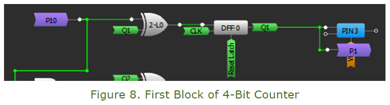
Workings of a single block of counter
The first block of the counter is enabled by cross-matrix connection P10 (Enable Write). The XOR gate (2-L0) then sets its output high, which sets the ‘DFF 0’ output high. CLK is set to have a time period of 104μs through OSC and CNT0/DLY0 block settings.
Every 104μs the clock input checks the DFF 0 block input (coming from XOR gate 2-L0) and sets it high or low. The high Q1 output is then passed through the AND gate (3-L0) for the block (Fig.8).
During the next cycle of CLK, the high Q1 at the input of the XOR gate (2-L0) toggles its output to zero and it is passed to the next block. So the output of the t block toggles between 0 and 1 for every clock cycle of the CLK.
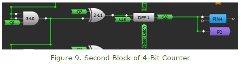
As shown in Fig.9, the second block of the counter is similar to the first except the enable input is coming from the first block (3-L0 output). The next two blocks are also similar to the second block.
1.3 Reset Mod-10 Counter
The LUT (4-bit LUT0) resets the counter once it reaches its 11th state (10112).
1.4 Concatenating Start bit, 8 digital status bits and Stop Bit
In this phase, the counter outputs trigger one of the 10 bits (start bit, 8 button status and stop bit) to be routed to PIN 12 one at a time.
For more details on how to send 8-bit serial data please see AN-1131 8 Channel Digital Input Data Acquisition Card using LABVIEW.
1.3 Reset Mod-10 Counter
The LUT (4-bit LUT0) resets the counter once it reaches its 11th state (10112).
1.4 Concatenating Start bit, 8 digital status bits and Stop Bit
In this phase the counter outputs trigger one of the 10 bits (start bit, 8 button status and stop bit)
to be routed to PIN 12 one at a time.
For more details on how to send 8-bit serial data please see AN-1131 8 Channel Digital Input Data
Acquisition Card using LABVIEW.
Modifying ESP-01 Module Code for Using It with Any Wireless Network
As wireless networks may have a different configuration from the one used in this project, therefore some particular changes are required for modifying the ESP-01 module code to suit the wireless network it is connected to:
(i) Setting name and password of Wireless network
The name and password of the wireless network needs to be set in line 34 and 35 of ESP-01 module code respectively.
Line 34: const char* ssid = "* * * * *"; // Name of wireless network
Line 35: const char* password = "* * * * *"; // Password of wireless Network
(ii) Setting a static Private IP address for the ISP
In order to set a fix private IP address for accessing internet, line 48, 49 and 50 of the code needs to be set according to the wireless network settings.
Line 48 : IPAddress ip(192, 168, 10, 100); // IP Address set to 192.168.10.100
Line 49 : IPAddress gateway(192, 168, 10, 1); // Default Gateway set to 192.168.10.1
Line 50 : IPAddress subnet(255, 255, 255, 0); // Subnet mask set to 255.255.255.0
The gateway and subnet mask of the wireless network will be fixed and they cannot be changed. However, you have the liberty to choose any unused IP address of the network.
After making these changes in the ESP-01 module code, it is uploaded to the module via Arduino IDE.
Practical Example
After setting username, password and private IP address for the ESP-01 module code it is connected to GreenPAK SLG46620V as shown in Figure 5.
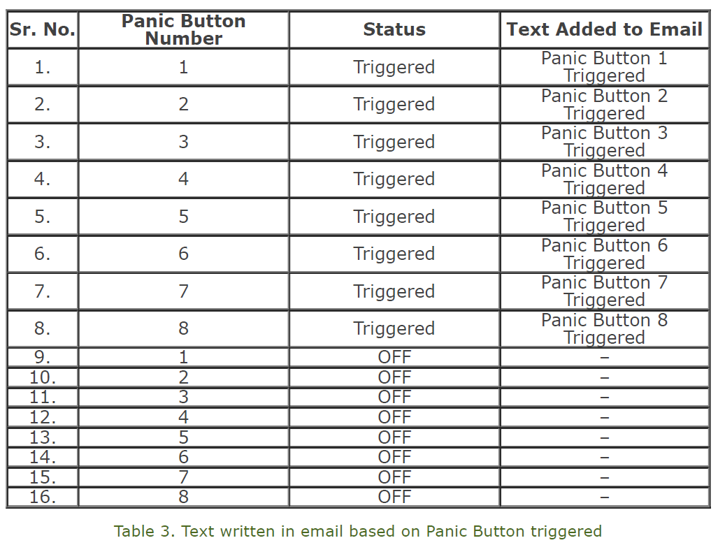
The email sent to a target email address in case of any event that is tabulated below (Table 3).
Here smtp2go server is configured for an email address. For more details on how to set the smtp2go server please visit this link.
2. For two or fewer panic buttons
Using two or fewer inputs scheme is quite simple. The inputs are attached to the two IO’s of the ESP-01 module. If any of the inputs are high, the attached Digital Input of ESP-01 reads high. The ESP-01 code can be easily configured to send an email to the selected email address in this event.
Power consumption
The overall power consumption of this complete design is very low, on the order of 500μA. The major contributors of this current consumption are 320μA for the ADXL335 and 80μA for the ESP8266. Thanks to this low power consumption, the device will be able to run for a long period of time.
In addition, the ESP-01 module can be adjusted to run in deep sleep mode. For details, please visit this website.
Conclusion
In this project, we developed an elderly care alert system that can detect fall events and send alert messages to an email address. Additionally, the panic button can be reset manually.
Since this is a low power consumption device, it can run for long periods of time on a single charge. It has the capability to detect a fall event automatically, which is a major asset since the elderly person who suffered the fall may be unconscious and unable to trigger the help call.