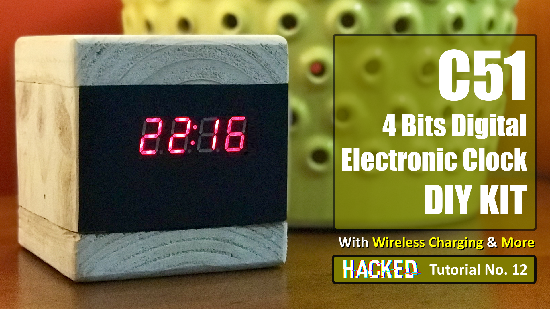
Had some spare time this weekend so went ahead and assembled this AU$2.40 4-Bits DIY Electronic Digital Clock.
Had some spare time this weekend so went ahead and assembled this AU$2.40 4-Bits DIY Electronic Digital Clock which I bought from AliExpress a while ago.
I bought this DIY kit from "HESAI 3C Electronic Components Store" from AliExpress for just AU$2.40. I have provided the store's link in the description below. The packaging was good and the item was delivered to me in just 15 days.
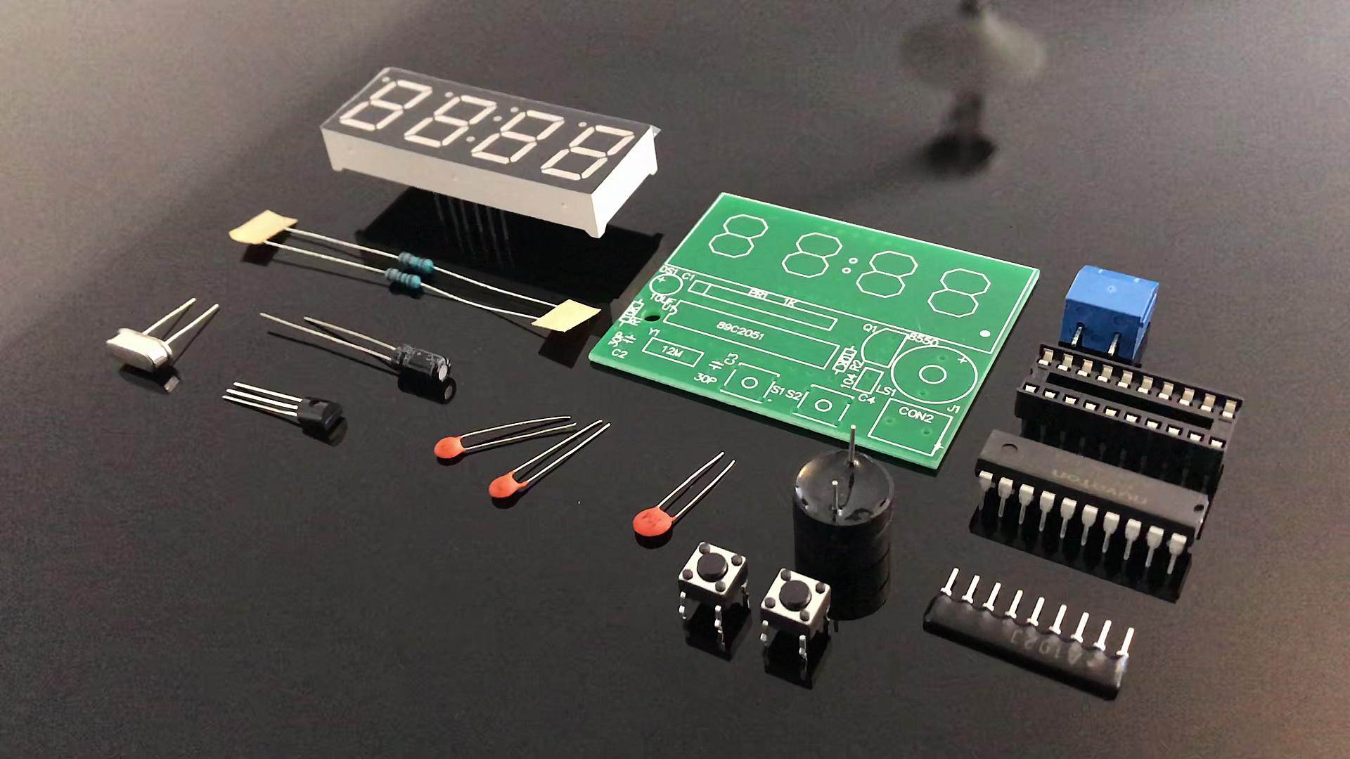
The item came with a circuit diagram and a list of components included in the packaging. Including the instruction sheet there are 18 items in this packet. You can find a scanned copy of the circuit diagram in the description below.
Frankly speaking, by looking at the components it doest look like you really need to be an electronic genius to assemble all these components. I guess all you need is just a general purpose soldering kit and a bit of your spare time.
Soldering
The board is actually drawn out with all the shapes of the components on it, so even if you don't know what the components are its really easy to find the right place for it. I am going to install the components from top to bottom so that I have easy access to all of them while soldering.
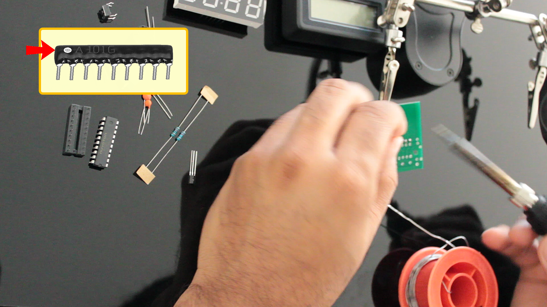
Lets first solder the 1K PR1 resistor pack to the board. One end of the resistor pack has a white dot on it. The white dotted side sits on the square facing the left side of the clock. After that, I am soldering the 8550 PNP transistor to the board. Just match the 'D' of the transistor to the 'D' drawn on the board and you will never get it wrong.
Next, I am soldering the 10μF capacitor. The +ve terminal or the long leg of the capacitor slides into the hole that has a plus next to it.
It actually doesn't matter what order you are solder the components on the board. The reason I am soldering them from top to bottom is to have easy access to the components when I am putting them on the board.
After soldering the base of the IC I am soldering the 2 x 10K resistors and the 3 ceramic capacitors to the board. Next, I am soldering the 12MHz oscillator crystal and the buzzer to the board. The positive leg of the buzzer slides into the hole which has a plus mark on it. After that, I am soldering the 2 x push buttons and the screw terminal block. I really don't like the concept of having the buttons in the front so, I will later move them to the back of the unit. The supply voltage can be between 3v to 6v. This clock also comes with 2 different alarm settings. You can either set them up or turn them off if you don't need them. This clock only displays in the 24hr clock format. I don't know about you but I really like the 24hrs format so its actually a good thing for me.
OK, now the final bit, lets solder the 4-Bit 7-segment display and install the AT89C2051 IC to the socket. Make sure when you solder the 7-Segment the dot on the bottom right corner matches the dot on the board. These displays consume a hell lot of current so, before creating the enclosure I will do a bit of maths to estimate how long the clock will last on a fully charged battery.
Testing
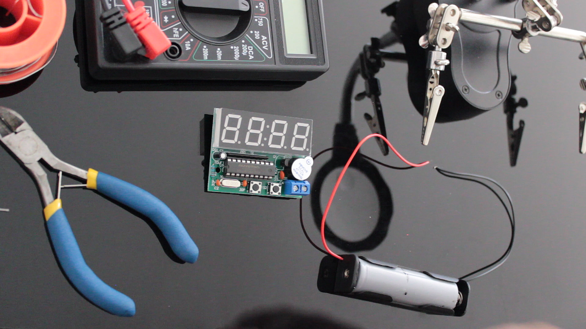
Once everything is soldered its time for us to do a quick test. Looks like everything is working the way they should, so lets now do the math and find out how many hours this clock will last without recharging the battery..
Current Calculation
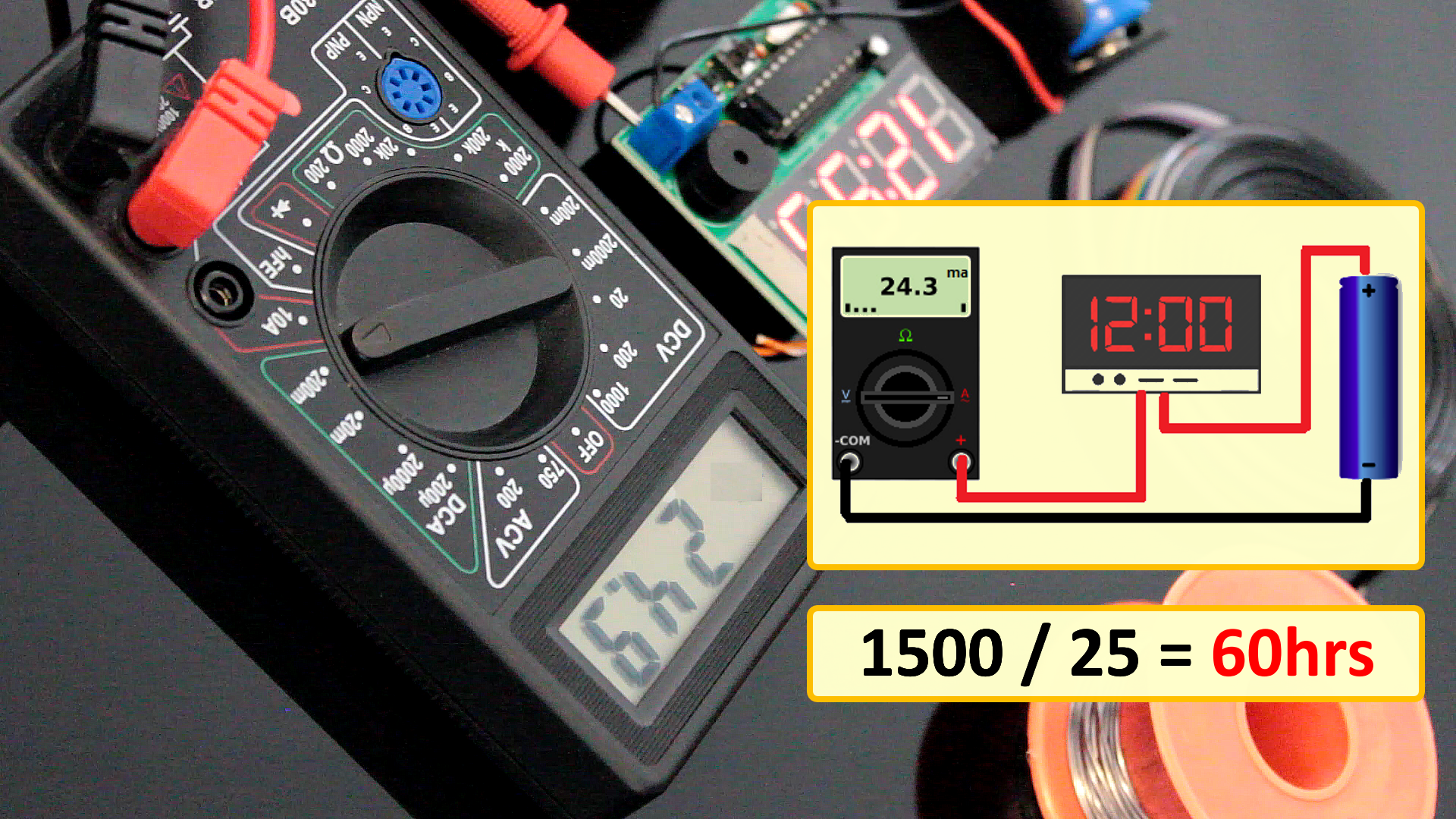
To calculate the current we need to setup our multimeter to current calculation mode. Then connect the multimeter in series with the clock to the battery. The 18650 battery I have holds 1500mAh current and by looking at the multimeter it looks like the clock consumes almost 25mAh current. So, if we divide 1500 by 25 we get 60hrs which is like 2.5 days.
1500mA / 25mA = 60hrs
60hrs / 24 = 2.5 days
Reset Button
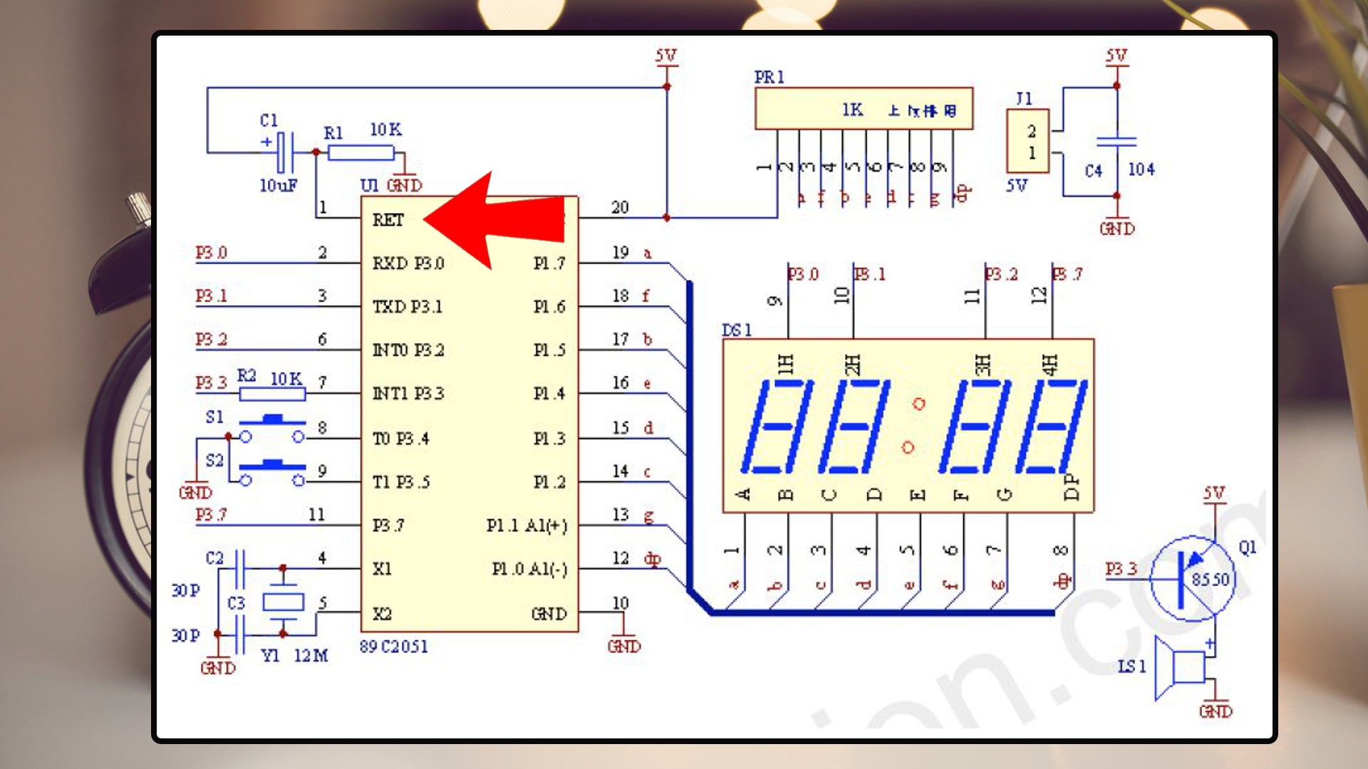
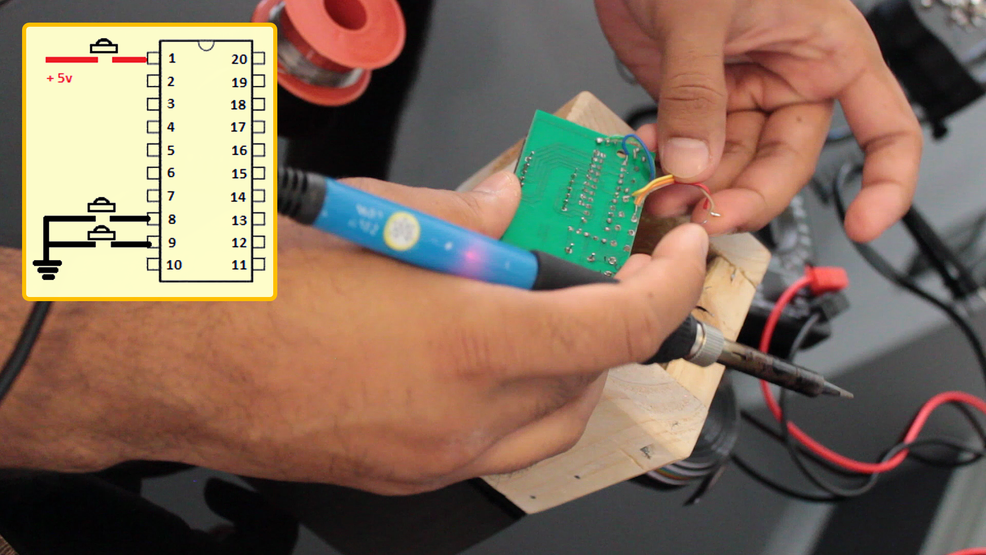
I have noticed that when you recharge the battery after it goes completely flat the clock displays all sorts of funny things except for the time on the display. So, adding a reset button to this clock wood be a good idea. Went back to the clock's manual and looked into the circuit diagram. Looking at the circuit you can see that Pin 1 of the IC is the Reset pin. Digging a bit further, you can easily figure out that to reset the IC you just need to set the pin to HIGH. So thats it, bingo. Lets do a quick test and see if I have hit the jackpot or not. Oh yes, that bloody works. Cool, now lets go ahead and create the wooden enclosure for this clock.
Woodworking
While cleaning my store room I looked at the pile of scrap wood I have in there. I was shocked to see the amount of crap I have collected overtime. Its like, my scrap pile explodes every time I build a new project! Bigger the project, the bigger the pile of scrap wood! So, I used a bit of it to create a nice looking enclosure for this clock.
I also added few upgraded to this small project which I am going to show you in the video.
Installing the Push Buttons
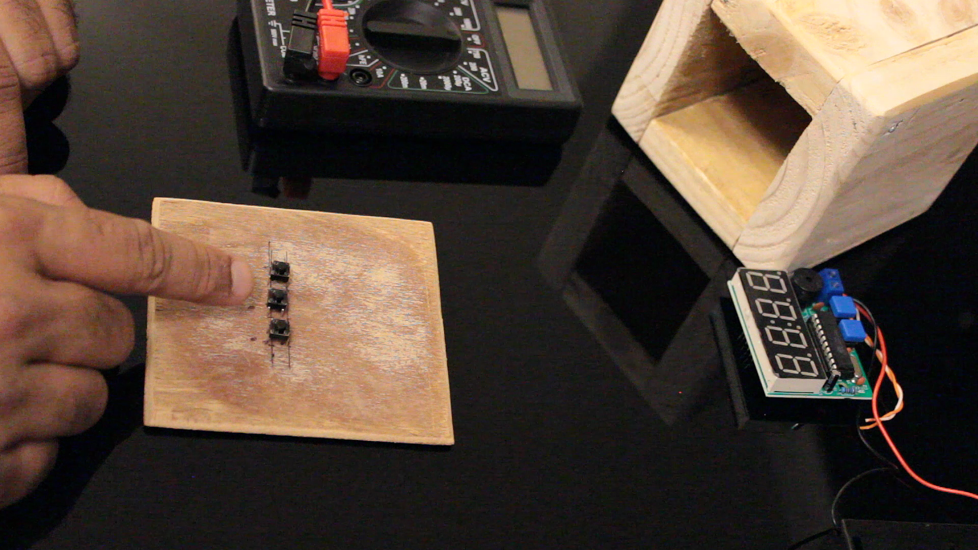
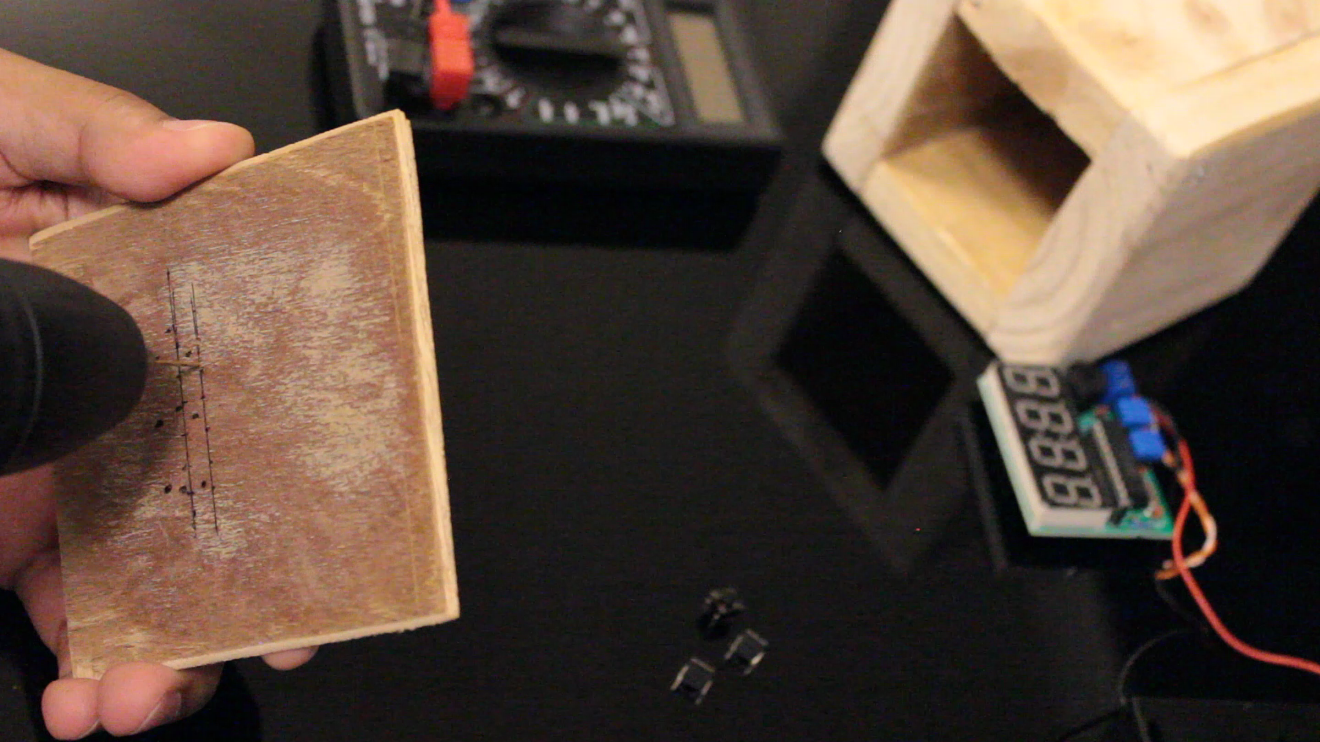
As discussed earlier I am moving the pushbuttons from the front to the back of the unit. I am also adding a reset button along with the other two buttons to the back panel. I choose plywood to create the back panel as it has less thickness than a pallet-wood.
Using the thinnest drill bit I am drilling all the holes required for the 3 pushbuttons. After that I am soldering a 6 way ribbon cable to the pushbuttons. It was actually a bit of a challenge to solder the ribbon to the buttons, so to hold the cable tight I am adding a bit of hot glue to it.
Installing the TP4056 Charging Module
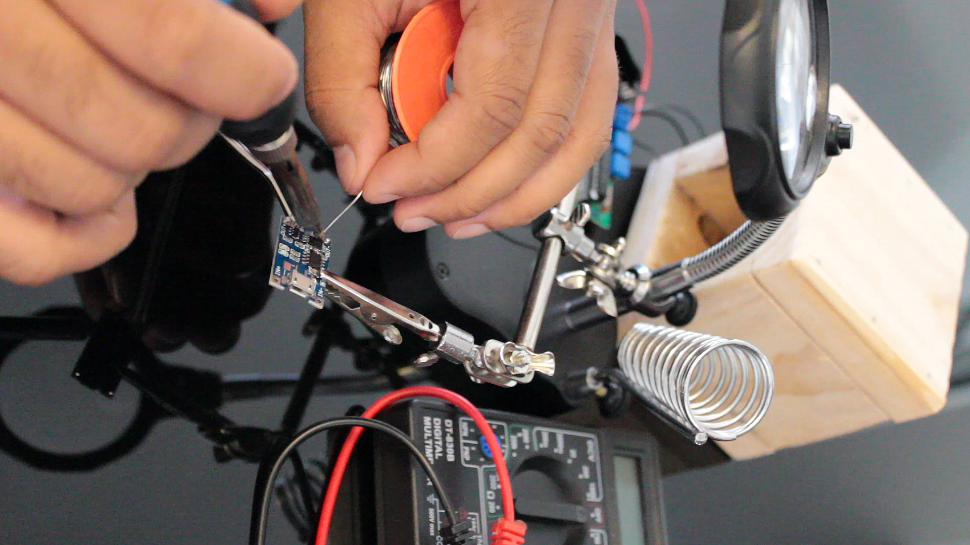
Next, I am going to install the TP4056 battery charging module with the protection IC to the unit. The protection IC protect the 18650 battery from overcharging and over-discharging. If you want to know more about this module please check out my tutorial number 2 "DIY - Solar Battery Charger". After drilling the right size hole in the back-plate I am going to hot-glue the module into it.
Installing the Wireless Charger
Ha ha, I became a bit lazy and instead of using nails or screws to stick the back plate, I just hot-glued it to the back of the unit.
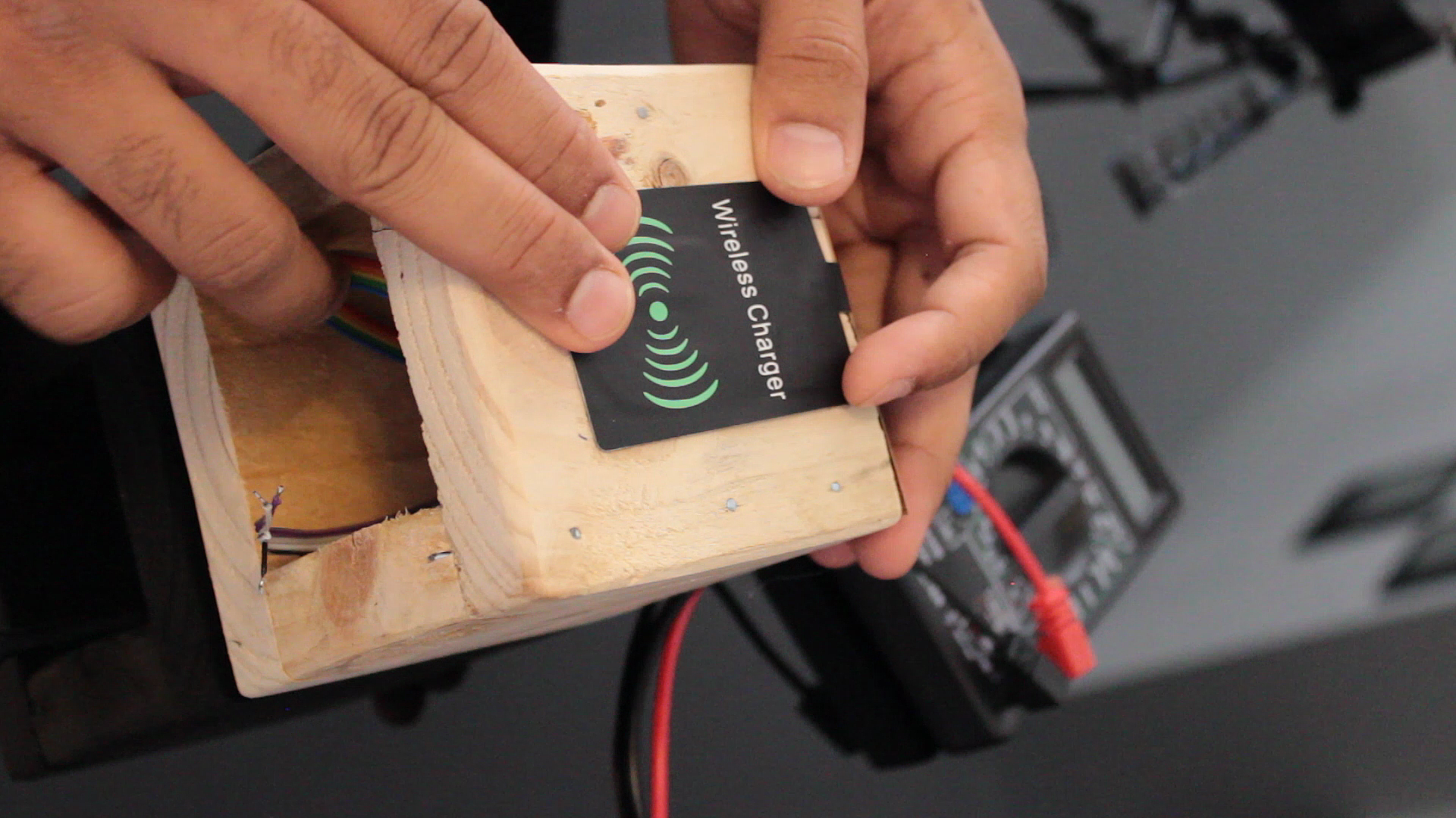
After that I plugged in this 'wireless charging receiver' to the TP4056 charging module which I also bought from AliExpress for $3. If you don't want to use a wireless charger you can either use a step-down converter or micro-USB charger.
Connecting the Pushbuttons
Once the backplate is in place I am soldering the push buttons to the clock. The reset button connects to the +ve and pin number 1 of the MCU. The other two pushbuttons will just replace the ones in the front.
Connecting the Charging Module and Battery
Now lets connect the battery and the charging module to the clock.
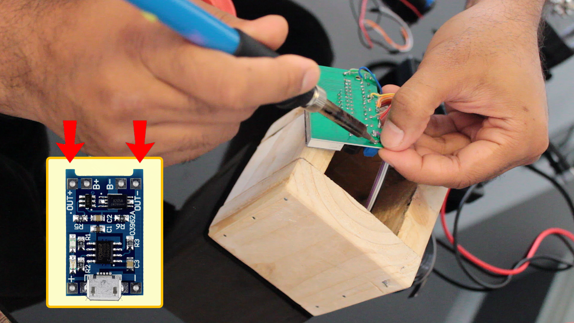
Connect the OUT+ and OUT- of the TP4056 module to the +ve and -ve input ports of the clock. Next I am installing the 3.7v 18650 battery using hot-glue inside the wooden enclosure. Once fitted I am connecting the B+ and B- ports of the TP4056 module to the +ve and -ve ends of the battery. Thats it, we are almost done.
Installing the Faceplate
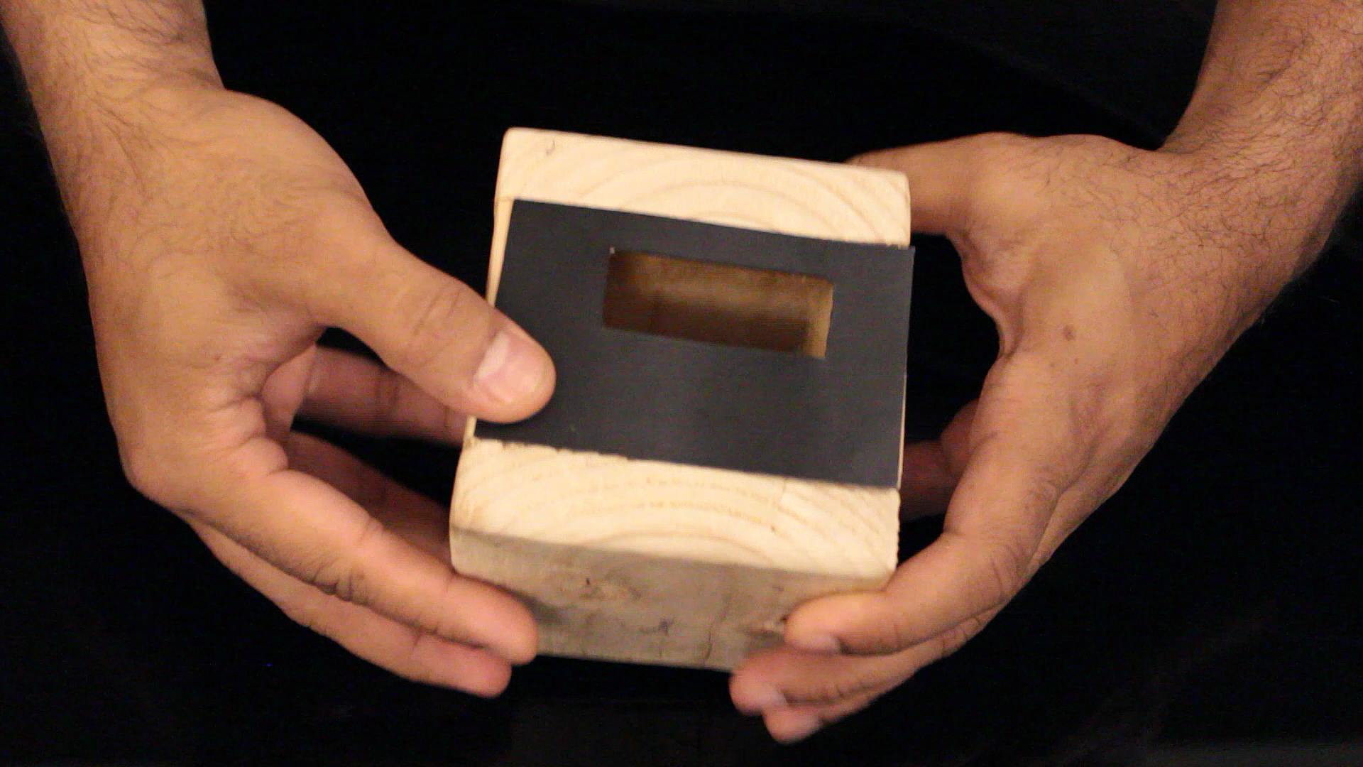
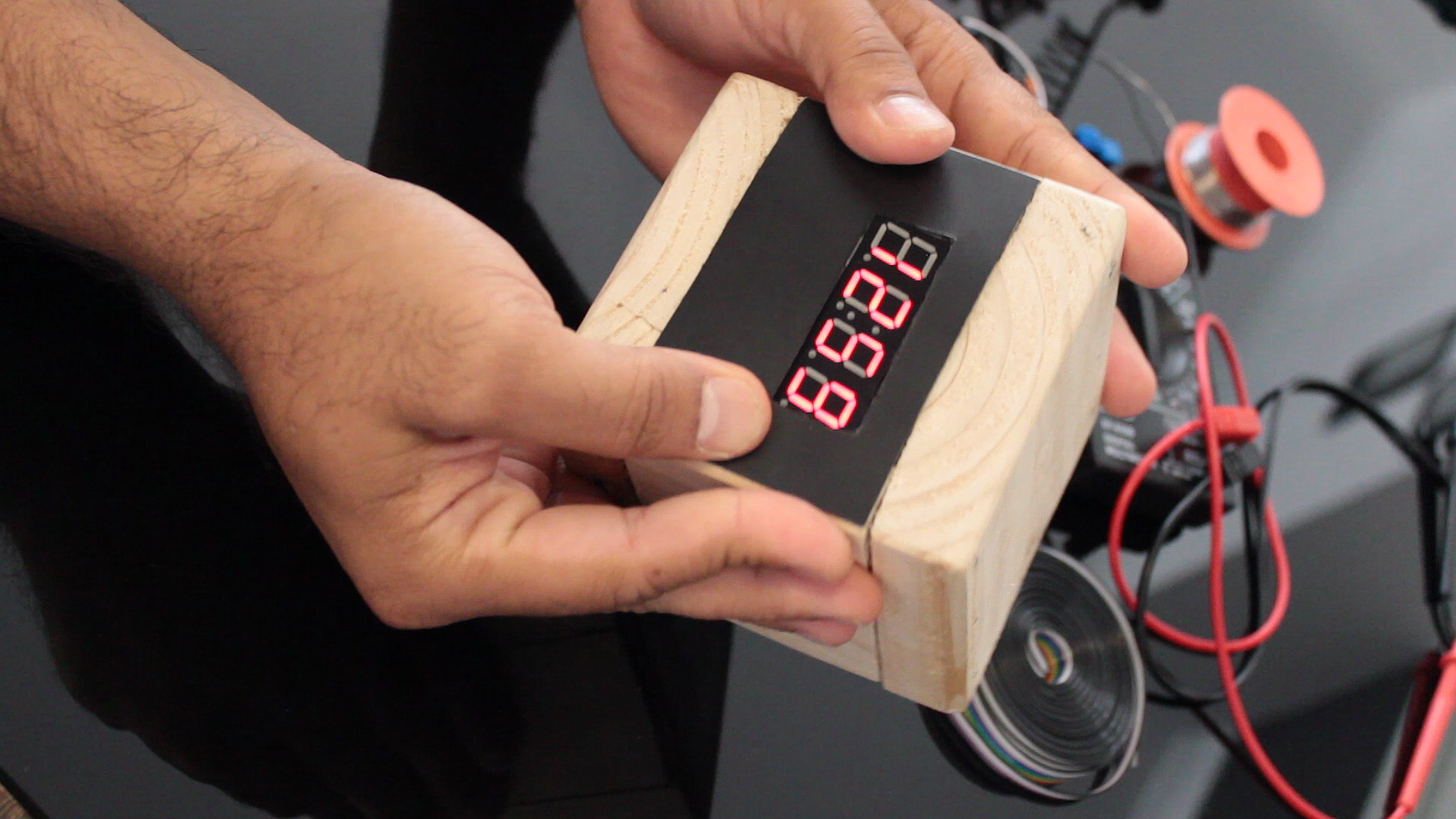
To finish up the project I am going to stick the 7-segment display to the faceplate and then hot-glue it to the front side of the wooden enclosure.
Setting Up the Clock
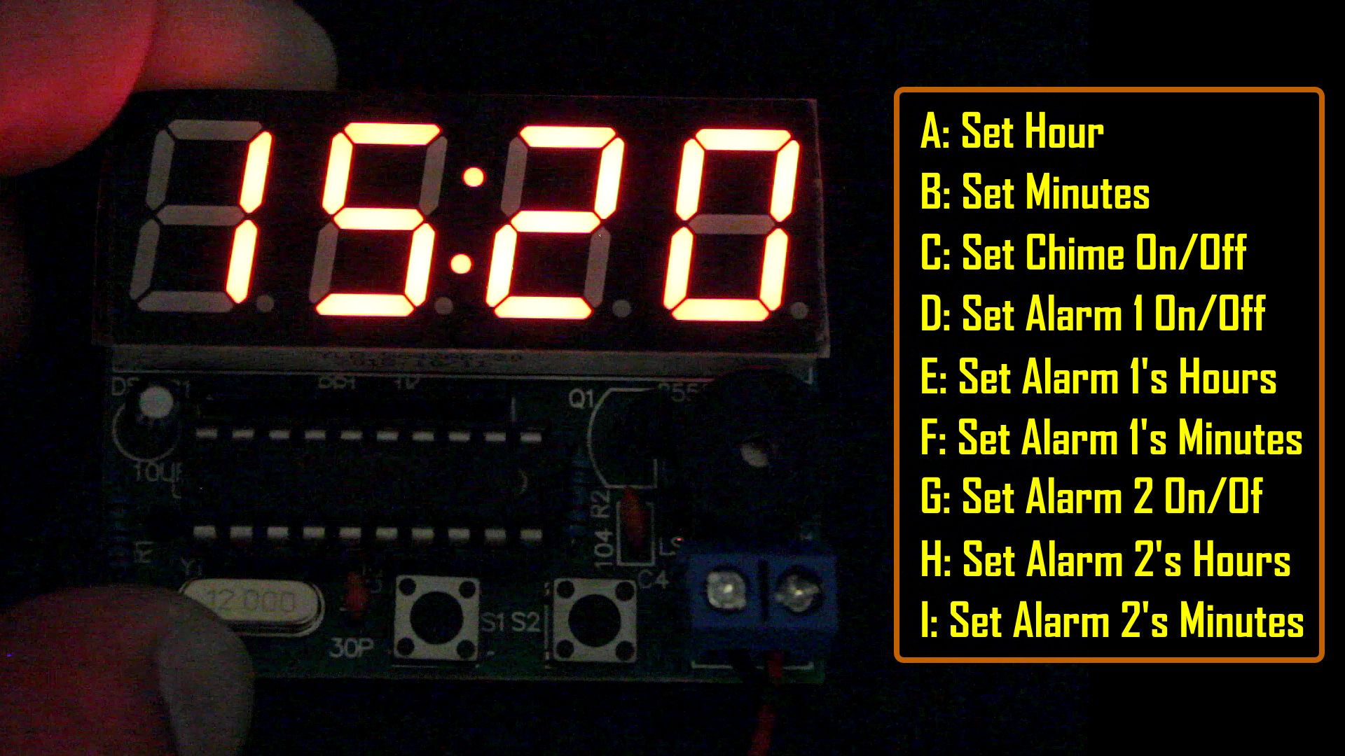
Programming is done using the two pushbuttons S1 and S2. In my project, I am calling the B1 and B2.
Hold the B1 to enter the clock settings mode
A: Set Hour - press B2 to change the hour and B1 when done
B: Set Minutes - press B2 to change the minutes and B1 when done
C: Set Chime On/Off - press B2 to turn it on or off and B1 when done
D: Set Alarm 1 On/Off - press B2 to turn it on or off and B1 when done
E: Set Alarm 1 Hour - press B2 to change the alarm hour and B1 when done
F: Set Alarm 1 Minute - press B2 to change the alarm minutes and B1 when done
G: Set Alarm 2 On/Off - press B2 to turn it on or off and B1 when done
H: Set Alarm 2 Hour - press B2 to change the alarm hour and B1 when done
I: Set Alarm 2 Minute - press B2 to change the alarm minutes and B1 when done
When the alarm starts beeping you need to press B2 to turn it off. There is no option to put it on snooze; however, as this clock has 2 alarms you can set them at an interval of 10 or 5 minutes to sort of mock the snooze option.
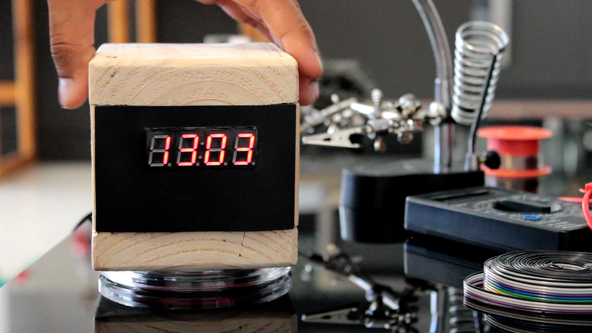
This clock is really very nice and accurate. Great for all the DIY lovers and for those who like electronics. I really enjoyed building it. In the night I charge my phone with the wireless charger and in the daytime the clock sits over it. Wireless charging gives this clock 100% mobility. I can take it with me to the shower, when I am having food or even when we go out for picnic.
Few things you guys can add to this project: * A transparent sheet for the faceplate so that only the lit up digits are visible * Remove the charging indicators from the TP4056 module and add two LEDs at the back to know when charging is happening and when the unit is fully charged. * LDR to dim the 7-Segment at night
Links
The watch/clock is available at the HESAI 3C Electronic components store. Cost: AU$2.32 / piece
Kit Model: YSZ-4 Supply voltage: 3V-6V PCB Size: 52mm * wide 42mm
Function:
1. Seconds correction (for precise School)
2. Switch to every minute independent display interface
3. whole point of time (8-20 o\'clock chime can be turned off)
4. Two alarm settings (you can turn off the alarm function)
Kit Features:
A. 0.56 inch special red digital clock for display;
B. Import AT89C2051 for master chip;
C. 1.2mm thick PCB made from military grade FR-4 board;
D. accurate travel time, travel time error range error -1 to +1 seconds every 24 hours.
