The GreenPAK™ device can be employed in simple salinity measurement applications using low cost materials and techniques
The GreenPAK device can be employed in simple salinity measurement applications using low cost materials and techniques.
This document explores the use of the SLG46531V along with the SLG88102V for the measurement of salinity in drinking water. It is to be noted that the procedures documented can be used for different Electric Conductivity (EC) values; this means that this implementation can be used in a wide range of alternate applications such as hydroponics agriculture, chemical readings and more.
1. Theory of sensing
Water salinity is, as the name indicates, the quantity of salts present in a certain quantity of water. In order to measure this value, we need to correlate it to an electronic reading; in this case we correlate the salinity to a voltage.
This can be achieved by analyzing the conductivity of water. At a given state, distillated water has a specific EC (Electric Conductivity); the change in its EC can thus be related to the quantity of salts dissolved in it. A voltage divider can be used to analyze the EC of the water to get an idea of its value; the higher the EC, the lower the resistance presented by the probe will be. This, in turn, corresponds to a lower voltage in the voltage divider.
The Electric Conductivity uses a unit called Siemens (S) and for this application we will be using mS/cm.
Usually the EC is measured using AC voltage because DC polarizes the liquid in the probe rendering the readings useless. A quick measure using DC can however be made if we use a pulse and then wait a few seconds for the next reading; this avoids polarizing by not letting the voltage reach the polarizing point.
Also, when the voltage is cut off the voltage divider, the liquid between the plaques of the probe returns to normal.
We will be using the previously mentioned method (Turning on for enough time to make the reading, and then turning the voltage off for a longer time than it was turned on.), in a system that periodically reads the EC and displays the output with a set of LEDs.
2. Designing the sensing circuit
We can design our own probe or measuring cell, using two traces of a conductor with a known area and distance between the two traces. They need to be parallel to each other and the liquid must also be between the traces.
To get EC we need G (Conductance).
The Conductance is defined as:
G = EC × A / L
and we define A/L as K.
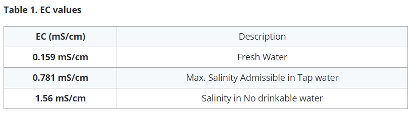
For this application we will suppose a K constant of 3 and we will be looking for specific EC values shown in Table 1.
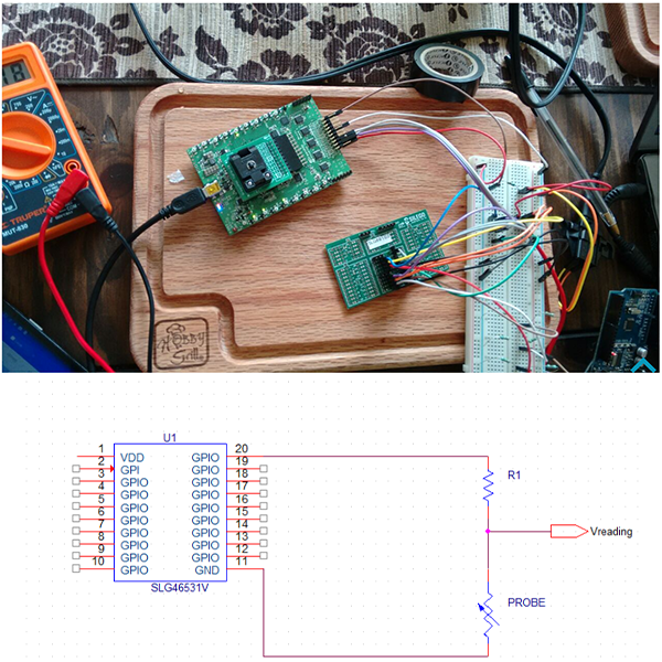
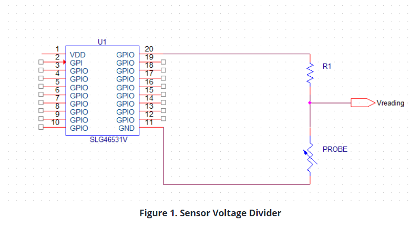
We need to know the range of voltage we will be obtaining from the voltage divider (V reading) as shown in Figure 1.
We calculate an approximate resistance for the probe after supposing a minimum and a maximum range of EC values using Table 1, and implementing the following formula:
R_Probe = 1000 / (EC × K) (1)
(1) Can be reached once we acknowledge that G = EC*A/L and G = 1/R.
1 / R = EC × A / L
L / (A × EC) = R = L / A × (1 / EC)
And finally K = A/L so L/A = 1/K
R = 1 / (EC × K)
EC is in S/cm so we multiply by 1000 to use mS/cm.
Note this formula is in units of mS/cm.
Moreover, the formula does not cater for the change in T, so the solutions must be at a range between 20°-25° C°. To cater for T we can use the following set of formulas:
EC25 = EC × (1 + .020(T - 25)) and R = 1000 / (EC25 × K) (2)(3)
But this time, we will not be catering for the value of T.
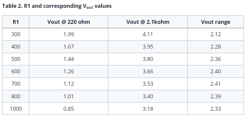
Substituting the EC values of 1.59 mS/cm and 0.159 mS/cm in (1), we can make a simple look-up table with several values for R1, for us to select from.
Note that 220 Ohm and 2.1 kOhm are the resistive values that are expected to be reached by the probe.
This way, we know that we can have a maximum of 2.41 volts between EC values of 0.159 mS/cm and 1.59 mS/cm.
This entails that we can sense using these 2.41 volts; the EC ranges between 0.159 mS/m and 1.59 mS/cm. In order to keep the rest of this simpler, we will focus on the EC values of 0.159 mS/cm, 0.781 mS/cm and 1.59 mS/cm as these values have great significance for drinking water. We also have to point out that the R1 resistor will have a value of 700 Ohms.
3. Limiting the Readings
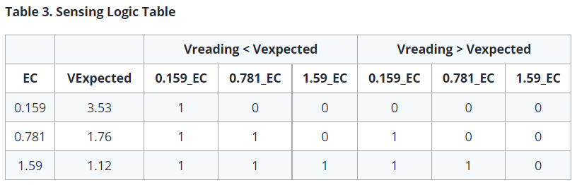
Since we are only looking for three EC numbers, we can obtain the expected voltage reading for them and use the SLG88102V to sense the values in order to obtain 3 digital outputs. We do this because the SLG46531V doesn't have an ADC. We can see the logic expected by the use of the SLG88102V in Table 3.
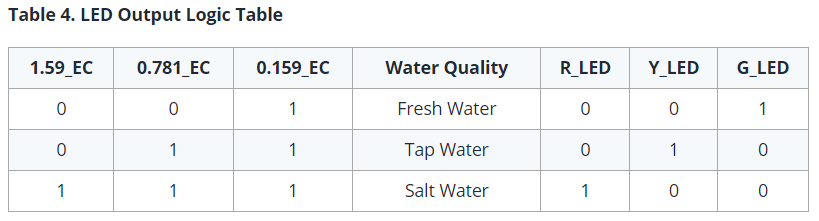
We will be using inverted logic when the voltage sensed is bigger than the voltage expected. In such a scenario, the output of the SLG88102V will be LOW; otherwise it will be HIGH. Table 4 further shows this logic.
We can depict those three water quality standards as 3 LEDs (Green, Yellow and Red) and can thus measure the limits of drinkable water.
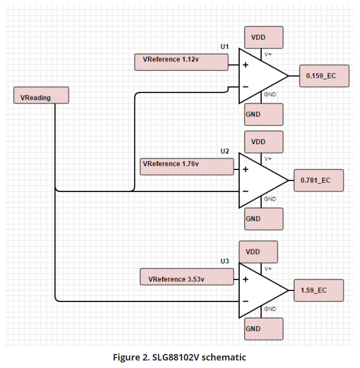
The SLG88102V has four OPAMPs; three of them must be configured as a comparator, just as it is shown in Figure 2.
It is not compulsory to use the three thresholds; we can use just two of them to mark two different levels. In such a case, we could also use the Dual PAMP SLG88101V.
VExpected can be obtained from Table 3.
When Vreading is bigger than VExpected, this configuration outputs the Value of LOW; it’s VDD when V reading is not big enough, which makes the three outputs become our 3-bits.
We can obtain the VExpected using voltage dividers on another PIN configured as a digital output.
The comparator’s outputs will need to go to the selected PINs in the SLG46531V. This can be viewed in Table 3.
4. Programming the SLG46531V
First we define three pins as digital inputs: PINs 3, 4 and 6 (1.59_EC, 0.781_EC and 0.159_EC respectively). These 3 PINs will be reading continuously, but since we are sensing every 6.34 seconds, we need to get the reading and interpret it at the same moment that we are sending the reading pulse. We achieve this by implementing a logic function using the same signal i.e. sent every 6.34 seconds.
As the SLG46531V has a fast response, the duration of the pulse does not give enough time to the voltage to reach the thresholds needed for the readings. So, we have to add a delay in the output of the counter amounting to around 657 milliseconds.
The functions used are 3-Bit and 2-Bit LUTs that are programmed to only give a HIGH to PIN 13 (R_LED) when Vreading is lower than the voltage expected and when the EC is of 1.59 mS/cm. A HIGH is sent to PIN 14 (Y_LED) when the Vreading is bigger than the voltage expected from the EC of 1.59 mS/cm and smaller than the voltage expected for an EC of 0.781 mS/cm. Finally a HIGH is sent to PIN 16 (G_LED) when Vreading is bigger than the voltage expected from an EC of 0.781 mS/cm.
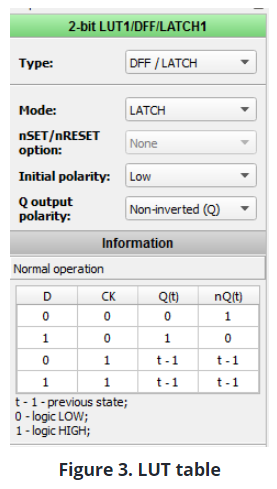
It would be hard to interpret the readings if the LED turns ON for only a few milliseconds; this means that we have to store the values of each reading. For that we use another configurable LUT (Look UP Table) and we select its Type as a LATCH. LATCH has a table of truth shown in Figure 3.
If we use the LATCH then we have to agree to a CLK signal; the LATCH will save the value when CLK is LOW and keep the past state when CLK is HIGH.
For the CLK we will once again use the Pulse i.e. generated every 6.34 seconds. This time we will first send it to an inverting gate; so when the pulse is set to LOW, the CLK in the LATCH will be in a HIGH state, and when it changes for a few milliseconds to LOW, it will store the reading. Finally, when it turns back to HIGH, the LATCH will keep the last stored value.
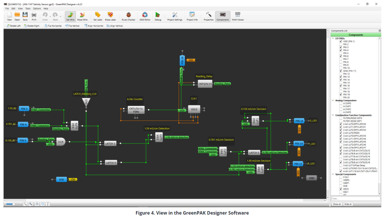
In Figure 4, we can see how the finished program looks. The logic gates present before the output PINs are there to make sure that only one LED will be turned on at a time. For that, we refer to Table 4.
The logic gates present before the output PINs are there to make sure that only one LED will be turned on at a time. For that, we refer to Table 4.
The logic was explained previously, and a file containing the project accompanies this note.
This method still leaves us plenty of resources to use inside the SLG46531V.
The final part is to connect the LEDs to ground using a resistor between the LED and ground to limit the current and also prevent any possible damage in the OUTPUT PINs, or in the LED.
It is also worth mentioning that if needed, a start button can be implemented in order to know when the first reading is being made.
This can be achieved using a latch to store the value of the button and using an AND gate to make sure that the readings are only done and stored after the button or switch is activated.
5. Another way round
As previously mentioned, the SLG46531V does not have a proper ADC; but if we don't need more resources from the SLG46531V and also don't have a SLG88102V available, then we can also use the three of the four analog comparators present inside the SLG46531V.
In this scenario, obtaining a more suitable voltage range requires a few more calculations in order for us to fully use the capabilities of the analog comparator.
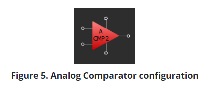
Shown in Figure 5, the analog comparator can have its negative input configured to an internal reference.
We can select diverse internal reference voltages for the comparator. However, the max reference voltage is around 1200 mV, which is not enough to cater for our current needs, and would also use up GPIO PINs.
Moreover, every analog comparator can only sense through a predefined PIN, which makes designing a little more limited.
However, the ACMP has an amazing function: the input gain.
It raises the effective max comparison voltage of 1200 milivolts to a whopping 4800 milivolts depending on the selected gain. Conversely, using the gain function increases power consumption, rendering necessary the use of WAKE/SLEEP cycles. In this application, slight ups and downs in the readings are not a big deal; but configuring said cycles would be extra work if the SLG88102V is used.
Here, if a Temperature compensator were to be implemented in the same SLG46531V, the PINs used for the ACMP could get used for this purpose instead.
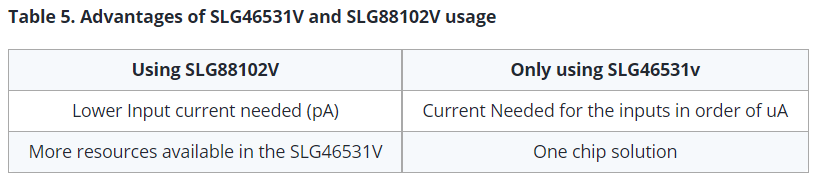
If we were to summarize the advantages, we would get the following.
6. Implementation
In this section, we will see the manufacture and the results of the device.
The reference voltages were obtained via a voltage divider whilst using the calculated resistances.
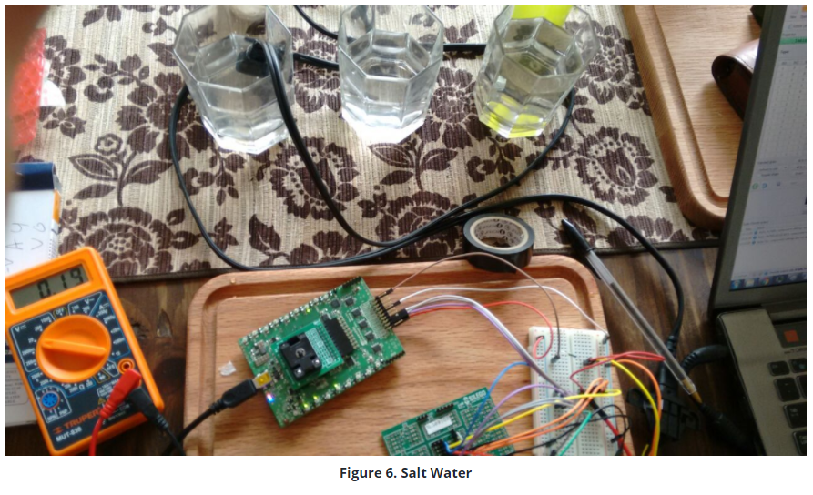
The device was built using a protoboard and an MCU to provide a stable 5V supply for the SLG88102V; the voltage dividers get used for the expected voltage values.
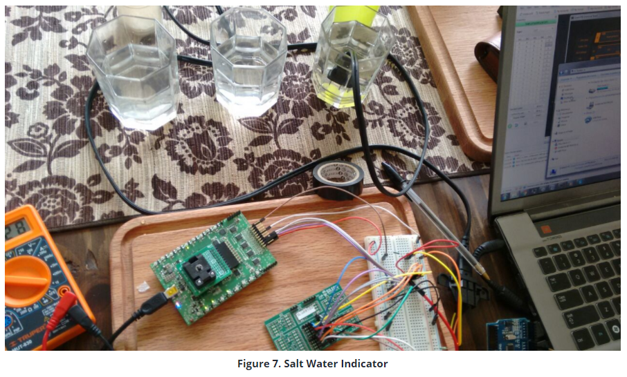
From left to right in Figure 6: Salt water, Tap water, Bottled Water.
Also in Figure 6, the output LED in the PAK5 development kit corresponds to the PIN 13.
The other PINs in the bottom part of the kit represent the constant HIGH readings coming from the SLG88102V. The output LED corresponds to R_LED in the designing so this means that the water is not drinkable. Figure 7 shows a close up of the LEDs
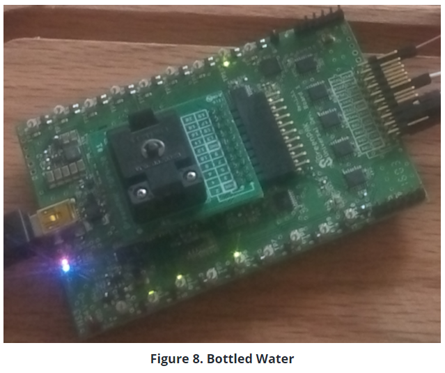
In Figure 8, the probe is in the bottled water container and the output LED corresponds to the G_LED, which was designed to be the LED indicating that the water was drinkable.
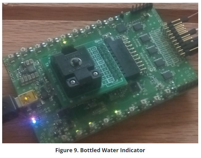
Figure 9 is a close up of the LEDs.
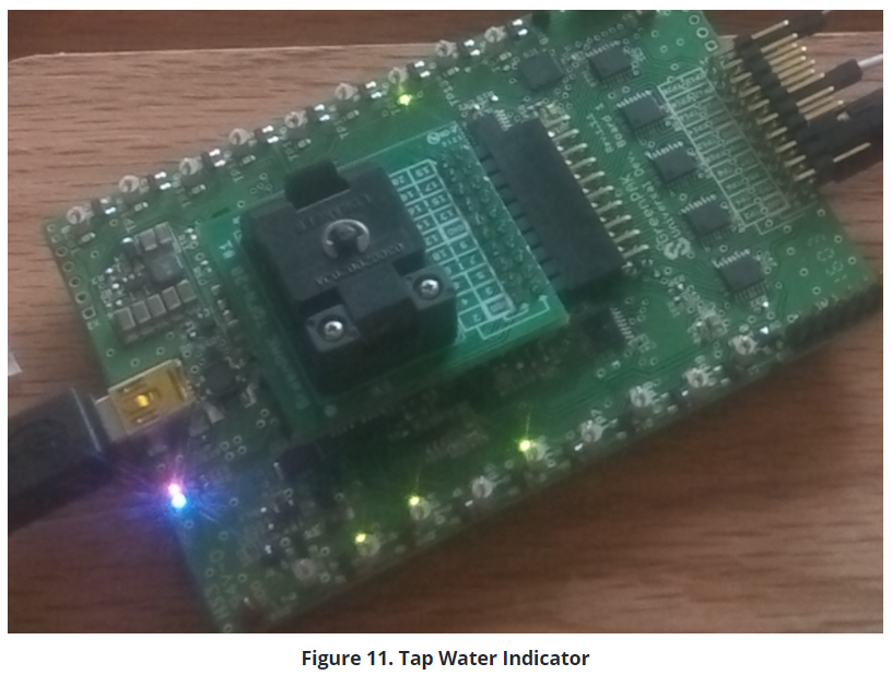
Finally in Figure 9, the probe is in the tap water container; the output LED is the one corresponding to Y_LED, which was designed to be the output for the salinity of city tap water.
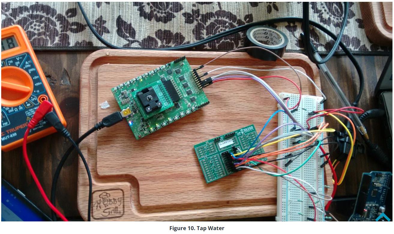
Figure 10 shows another close up of the LEDs that are “on” at the moment.
7. Probe selection
The probe selected was a 1-15 NEMA Type A Plug, which has a K of approximate 3 (2.9 to be precise).
The mentioned K, like the 1-15 NEMA, is a standard which should be true for the one used in this project and future ones.
K can also be obtained using the formula K = A/L. This can be used to design a new probe for other applications.
8. Notes regarding the scope of the application
Procedures documented in this project can also be used for other EC values, expanding possible end applications and use cases.
As mentioned before, T (Temperature) affects the conductance of liquids, but it doesn’t change it in a linear way; to adjust it, we can calculate another range of EC values.
Even if the present procedure does not include any temperature compensation, the formulas have been mentioned, if needed. It's only a matter of following the same procedure with a different set of values.
For example, if we were to measure the salinity of a reef tank, we would need to be reading an EC of 56 mS/cm as it is the ideal value. In this scenario, we can make a simple range: 56 being “ideal”, 55 being “low salinity” and 57 “high salinity”.
Then, we would have to calculate the maximum and minimum values of resistance that the probe could reach. After that, we would have to select a value for resistor R1, and follow that by calculating the voltages we would expect to see of the three levels of salinity.
Design the voltage dividers for the reference voltage and implement the 88102. Finally, we change the purpose of the same application.
It is worth noting that if we were to build the probe; stainless steel would be the ideal material to use as it would last longer in cases of repeated submersion in high salinity fluids.
Be sure to always rinse the probe with distillated water before and after exchanging solutions. This prevents the previous solution from contaminating the new one for more accurate readings.